


Suspended Ceiling Mount Backbox Modules | Instruction Manual | Installation
Bosch Security Systems | 15 May 2003
EN
|
12
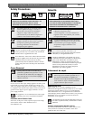
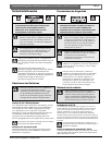
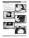
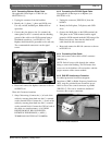
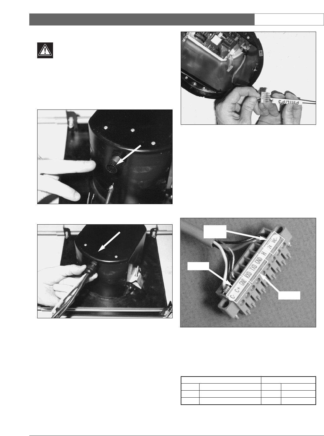
4.6 Connecting Power, Signal, and Video
CAUTION: Before proceeding, disconnect
power from the cable to be installed into the
unit. Be sure that the unit is of the proper line
voltage type (24 VAC) for line power being
used.
1. Route the wires through the backbox connector
opening (PHOTO 12 and PHOTO 13).
Photo 12: Wire Installation
Photo 13: Wire Routing Fitment
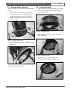
2. Make applicable wiring connections in accordance
with Connecting Line Power, Connecting Biphase
Signal Cable, Connecting RS-232 Signal Cable, and
Connecting Video Cable (PHOTO 14 through
PHOTO 17).
Photo 14: Connector Installation
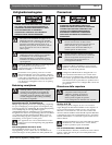
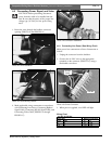
4.6.1 Connecting Line Power (See Wiring Chart)
Make power line connections to Power Connection as
follows:
1. Unplug the connector from the backbox.
2. Connect the 24 VAC wires to the appropriate
terminals on the connector (PHOTO 15) using a
flat-bladed screwdriver.
Photo 15: Power Connector
3. When power is applied, a red LED will light.
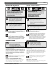
Wiring Chart
24 VAC, 40 VA Max
Wire Size Maximum Distance
mm
2
AWG m ft
118 75250
1.5 16 120 400
Biphase
24 VAC
Power
RS-232