


Suspended Ceiling Mount Backbox Modules | Instruction Manual | Installation
Bosch Security Systems | 15 May 2003
EN
|
13
4.6.2 Connecting Biphase Signal Code
Not applicable if data input is via RS-232 (see
SECTION 4.6.3).
1. Unplug the connector from the backbox.
2. Identify the (+) phase, (-) phase and GND wires.
Use only twisted, sheilded pair, Belden 8760 or
equivelent.
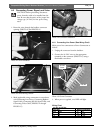
3. Connect the plus phase to the C+ terminal, the
minus phase to the C– terminal, and the shielding
ground of the cable to the GND terminal using a
flat-bladed screwdriver, (see PHOTO 15). The
Biphase shield should be grounded at one end only.
The recommended connection is at the signal
source.
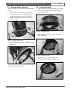
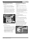
4. Route and connect the biphase connector as shown
in PHOTO 16.
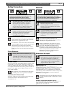
Photo 16: Connector Locations
5. Daisy Chain wiring: Connect the (+) of each of the
cables by inserting them both into the C+ terminal
on the terminal block. Connect the (-) of each of the
cables by inserting them both into the C- terminal
on the terminal block. Connect the GND of each of
the cables in a similar manner. A 110 OHM
RESISTOR MUST BE CONNECTED
BETWEEN THE BIPHASE (+) AND (-)
TERMINALS ON THE LAST CAMERA.
4.6.3 Connecting the RS-232 Signal Cable
Not applicable if data input is via Biphase (see
SECTION 4.6.2).
1. Unplug the connector (PHOTO 16) from the
backbox.
2. Identify the RxD phase, TxD phase, and GND
wires.
3. Connect the RxD phase to the RXD terminal, the
TxD phase to the TXD terminal, and the signal
ground to GND terminal marked GND using a flat-
bladed screwdriver. Note that the shield of the
cable should be left unconnected.
4. Route and connect the RS-232 connector as shown
in PHOTO 16.
4.6.4 Connecting Video Cable
Route and connect video cable to BNC connector
(PHOTO 16).
NOTE: Push all excess cable through the conduit
fitting or strain relief bushing. This will ensure that
excess wire in the backbox will not interfere with the
proper insertion of the camera module.
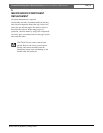
4.6.5 EMI/RFI Interference Protection
For added protection from Electromagnetic
Interference (EMI) or Radio Frequency Interference
(RFI), snap the provided ferrite around the power
cable as close to the control connector as possible
(PHOTO 17). This can be outside the backbox if
necessary due to space constraints.
Photo 17: Ferrite Placement
Power/Data
Connector
Video
Connector