


!
Table of Contents
1 DESCRIPTION
2 UNPACKING
3 SERVICE
4 INSTALLATION
5 EXPLODED VIEW
1 DESCRIPTION
The LTC9412/00 is a 12” pendant mount ceiling dome for
indoor applications. The housing top is black ABS plastic
2 UNPACKING
Unpack carefully. This is a mechanical equipment and should
be handled carefully.
Check for the following items:
• Model No. of unit
If an item appears to have been damaged in shipment, replace
it properly in its carton and notify the shipper. If any items are
missing, notify your Bosch CSS Sales Rep re sen ta tive or Cus-
tomer Service.
The shipping carton is the safest container in which the unit
may be transported. Save it for possible future use.
3 SERVICE
If the unit ever needs repair service, the customer should
contact the nearest Bosch Security Systems Service Center for
authorization to return and shipping instructions.
Service Centers
U.S.A.: Phone: 800-366-2283 or 408-956-3895
fax: 800-366-1329 or 408-956-3896
e-mail: NationalServiceCenter@ca.slr.com
Canada: 514-738-2434
Europe, Middle East & Asia Pacifi c Regions:
32-1-440-0711
For additional information, see www.boschsecuritysystems.com
Bosch Security Systems
2
2
2
2
3
14 November 2003
EN
2
LTC9412/00 Instruction Manual Introduction
4 INSTALLATION
This installation should be made by qualifi ed service personnel and
conform to the National Electrical Code and applicable local codes.
Please read these instructions carefully before
proceeding, and heed all cautions.
4.1. Remove contents from the box and check to be sure all pieces are
included.
4.2. Select the desired location for the installation. It must be a secure
mounting structure, and the completed installation must be able to
support 3 times its weight.
4.3. Determine the desired height for the unit. Measure from the
ceiling to the top of the housing (the housing is approximately 18”
tall). Add 8” for the interior of the LTC9412. Obtain 1/2” electri-
cal conduit and hardware to mount to the ceiling. Cut the conduit
to the measured length. Mount the conduit to the ceiling.
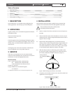
4.4. Slide the Clamp Connector and housing up the conduit so that
the end of the conduit is approximately level with the bottom of
the housing. Tighten the 2 Phillips head screws (Figure 1).
Figure 1 Slide housing and connector onto conduit
Clamp connector
with 2 Phillips head
screws
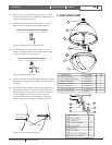
4.5. Completely seat the EMT con nec tor to the end of the con duit and
tighten the set screw (Figure 2).
Figure 2 Place the EMT connector on the conduit