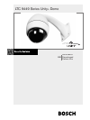
LTC 9449 Series | Instruction Manual | Installation
Bosch Security Systems | October 10, 2006
EN
|
8
4INSTALLATION
CAUTION: These units must be properly and
securely mounted to a supporting structure
capable of sustaining the unit weight. Use care
when selecting mounting hardware (not
supplied) for installation, the mounting surface
and unit's weight should be carefully
considered.
4.1 Pipe Mounting
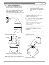
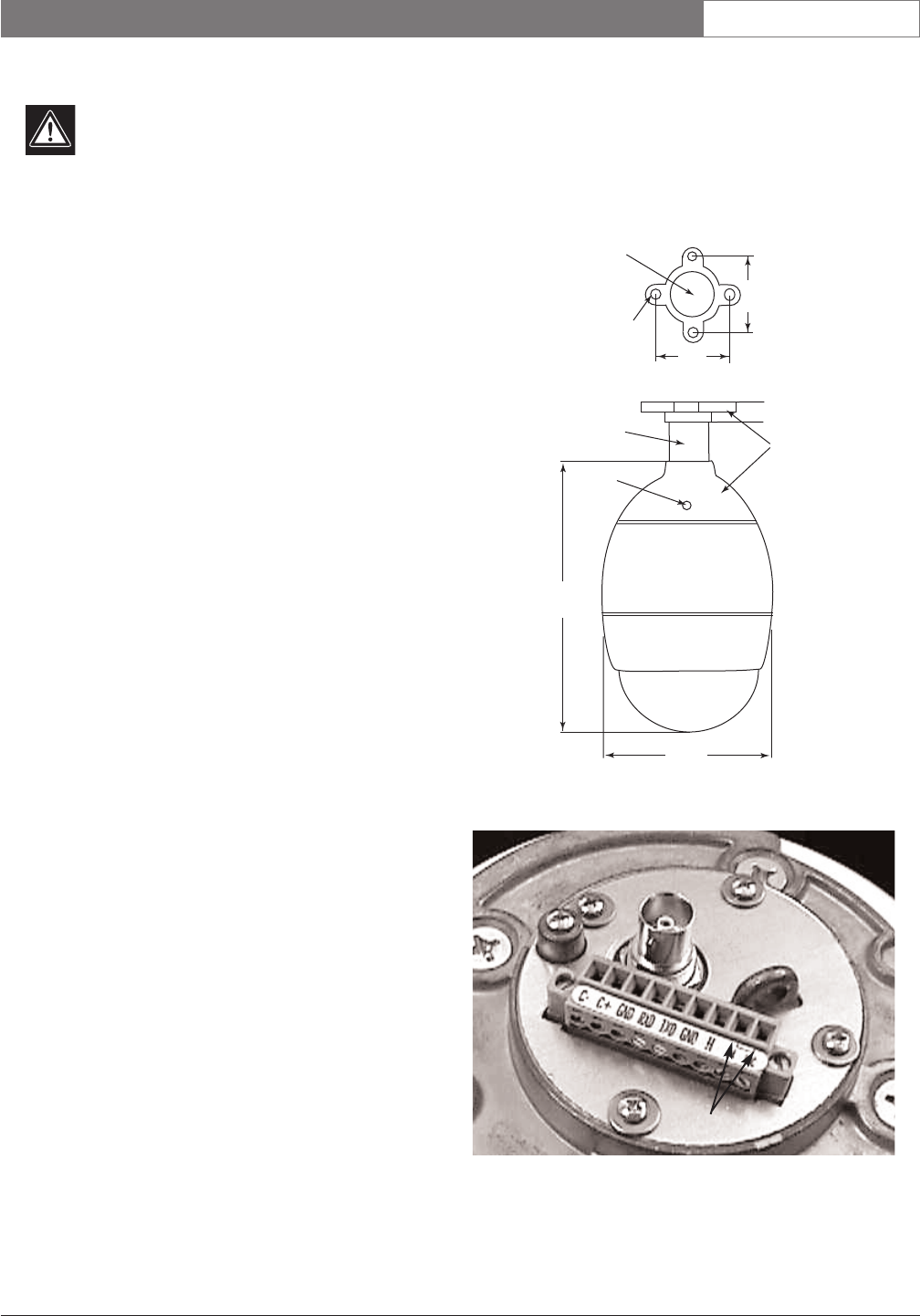
1. The Ceiling Mount (LTC 9543/00) is used to mount
the unit to the ceiling.
2. Attach a safety cable to an appropriate point on the
ceiling.
3. Feed the cables through the ceiling mount and
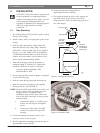
fasten the mount to the ceiling using 4 fasteners
(FIGURE 1). Allow enough cable for the length of
the pipe + 1m (3ft). 10mm (3/8in.) bolts/studs are
recommended. Bolts should be secured with nuts,
washers, and lock washers. Surface fasteners and
surface should withstand 270kg (600lb).
4. Each end of the pipe should be threaded to a
minimum length of 25.4mm (1in.). Pipe thread
standards which may be used are as follows:
American National Standard - NPT.
British Standard - BSP.
5. If metric pipe thread is used, an adaptor is required
at each end of the pipe.
6. Feed the cables through pipe and mounting cap.
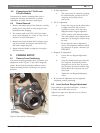
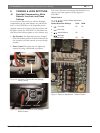
7. Make the electrical connection to the supplied
mating connector. (See FIGURE 2).
NOTE: On both 24VAC and 12VDC units, either wire
can go to either of the specified pins on the
mating connector. In multiple camera
installations using 24VAC units, connect the
wires to the same connectors to ensure proper
camera phasing.
a. Connect the 24VAC or 12VDC power
leads to the 24VAC pins and tighten
screws.
b. Connect the video lead to the BNC
connector located on the top of the
housing.
8. Connect the mating connector securely to the
connector on the connector plate.
9. Securely tighten the mounting cap onto the pipe to
approximately 44N.m (30ft lb).
10.Torque the pipe into ceiling bracket to
approximately 44N.m (30ft lbs).
11. If a significant length of pipe is used, support the
pipe with braces or guy wires to prevent the
swaying motion of the unit from being noticed on
the video display.
Figure 1: Ceiling/Pipe Mounting
Figure 2: Connector Plate
Wire Entry Hole
Mounting Hole
1-1/2in Pipe
with NPT
Threads Both
Ends (Not
Included)
Set screw (2)
LTC 9543
Ceiling Flange
with Gasket &
Mounting Cap
203
8.0
325
12.8
24.4
0.96
mm
in
88.9
3.50
88.9
3.50
Power Leads


