


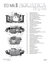
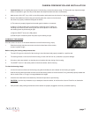
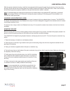
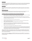
CONTROLS IN DETAIL
1. SHUTTER RELEASE LEVER: Pulling the shutter release lever back part way activates the camera meter and auto focus. Pulling the lever back all
the way res the camera.
2. MAIN DIAL ACCESS KNOB: Rotates clockwise and counterclockwise. Use alone or in combination with other controls to select
or set various camera functions or modes. In “Manual” the exposure mode controls the shutter speed settings (see camera manual).
3. LCD PANEL ILLUMINATOR BUTTON: Press to engage the top LCD panel illuminator.
4. ISO / FLASH EXPOSURE COMPENSATION: Press to select ISO speed or to select exposure correction of the ash*
* (please note this is only in the event a Canon ash in a housing would be used)
5. AF/ DRIVESELECTOR BUTTON: press to select either AF Mode or the DRIVE modes
6. METERING PATTERN / WHITE BALANCE MODE BUTTON: Press to select the appropriate metering mode and/or White Balance mode.
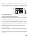
7. MAIN BULKHEAD CONNECTOR: To connect Flash Sync Cord. (Manual Nikonos Type by default other option available on request).
8. SECONDARY BULKHEAD CONNECTOR: For Flash Sync Cord. (Manual Nikonos Type by default other option available on request).
9. HYDROPHONE: This will record sound while video recording underwater, it is design to be effective underwater and will not function
properly if not immersed.
10. FOCUS/ZOOM KNOB: Turning allows manual focus of a single focus lens or rotation of the zoom mechanism of a lens.
11. FOCUS/ZOOM PINION GEAR: Engages and operates the focus or zoom gear attached to the lens.
12. LATERAL ACCESSORY BULKHEAD CONNECTOR: For additional accessories or control connector.
13. LENS RELEASE KNOB: activates the lens release button on the camera allowing easy removal of the lens.
14. LENS RELEASE KNOB LEVER: Applies pressure on the camera lens lock button
15. HOT SHOE CONNECTOR: connects the camera to the Flash Bulkhead. Slide this Connector into the camera Hot Shoe.
When detaching do not pull the cord as this might damage the electrical connections.
16. HAND GRIPS (X2): Left and right grip allowing the mounting of strobe arms and accessories.
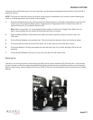
17. PORT RELEASE MECHANISM BUTTON: Press down to release the locking mechanism when installing or removing a port or extension.
18. REMOVABLE CAMERA TRAY: Used to attach camera and slide in housing.
19. BAYONNET MOUNTING FLANGE: allows the mounting of different ports and extension rings on the housing.
20. ACCESSORY BULKHEAD CONNECTOR: For additional strobe or remote control connector.
21. GRIP’S ACCESSORIES MOUNTING HOLES: Two 1/4-20 TPI holes on each grip are ready to accept TLC Base Brackets or TLC Base Ball
for strobe arms or accessories.
22. MODE DIAL PORT WINDOW: Enables viewing of the different release options
23. LATCHES: Two heavy duty latches with safety locks to protect against accidental opening.
24. QUICK CONTROL DIAL ACCESS KNOB: It rotates clockwise and counterclockwise. It can be used alone or in combination with other
controls to select or set various camera functions or modes. Refer to camera manual for in depth use.
25. AF-ON / AF-START / STAR ACCESS LEVER: This lever can be pull outward or inward to access both the AF-ON feature and the Star
customizable button, theses are important controls for video shooting and care should be taken to fully understand their working and subtleties.
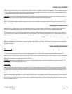
26. TOP LCD WINDOW: displays essential camera operating data.
27
. MOUNTING HOLE FOR ACCESSORY: a 1/4”-20 TPI hole is supplied to accept a TLC accessory or TLC base ball for mounting a
strobe arm or a modeling light.
28. REMOVABLE VIEWFINDER: A full view of the illuminated camera viewnder displays all necessary information.
This viewnder be removed and replaced with optional Aqua View Finder for a larger displayed image.
page 3