


L
o O
t 1
o
p uL
o O
t 1
o
p u
O
Loop ut
2O
Loop ut
2
L o O
t 3
o p uL o O
t 3
o p u
L
op
O t 4
o
uL
op
O t 4
o
u
n to
Mo i r 1
n to
Mo i r 1
Mo
nitor 2Mo
nitor 2
IR
In
(
on 1)
MIR
In
(
on 1)
M
O t (
n )IR
u Mo 2O t (
n )IR
u Mo 2
P e
ow
r
P e
ow
r
In uts
pIn uts
p
Camera
1Camera
1
C me
ra
2aC me
ra
2a
C
me
a
a
r 3
C
me
a
a
r 3
C
me a
a
r
4
C
me a
a
r
4
VideoVideo
oAudi
oAudi
PR
O
C
H
A
NN
E
L
M
T
V IO
NIS
C
H
A
NN
E
L
V IO
NIS
M
T
M
d l
o
e
P
-6
0
14
deV
i
o P
resent
deV
i
o P
resent
Came
ra 1
Came
ra 1
Camera 2
Camera 2
Ca
mera 3Ca
mera 3
Came
ra 4
Came
ra 4
RS
-232
RS
-232
me dj
T
i
A ustme dj
T
i
A ust
U
CA
T5
CA
M
ER
A
SE
Q EN
C
ER
H d
ol
H d
ol
oop Ou
1
L
t
oop Ou
1
L
t
Loo
p O
ut 2Loo
p O
ut 2
Loop Out 3Loop Out 3
Loo
p O
ut 4
Loo
p O
ut 4
Monito
r 1
Monito
r 1
Mon
t
2
i or
Mon
t
2
i or
R I Mo
n 1)
I n(R I Mo
n 1)
I n(
IR
Ou
t (M
on 2)
IR
Ou
t (M
on 2)
Pow
er
Pow
er
Inp
utsInp
uts
a 1
Ca
me
r
a 1
Ca
me
r
Camera
2
Camera
2
a
Camer
3
a
Camer
3
Camra
4
e
Camra
4
e
V
ieo
dV
ieo
d
Audio
Audio
O
P
R
H
AN
N
L
C E
TM
IS
O
V
I
N
H
AN
N
L
C E
IS
O
V
I
N
TM
o e
l M d
-
0
1
4
P
6
i resentV deo P
i resentV deo P
C era
am
1C era
am
1
Camera
2Camera
2
Camera 3Camera 3
a
Cmera 4
a
Cmera 4
S
R -23
2
S
R -23
2
T
m
sti e Adj
uT
m
sti e Adj
u
A C EC
T5
AM
ERA S
EQUENC R
HoldHold
6125
3112
4
5
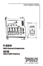
P-6014
TV (Monitor)
6210
6210
6210
6210
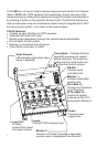
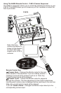
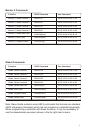
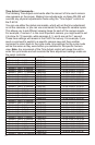
P-6014 Camera Sequencer Basic Application...
The primary function of the P-6014 is to sequence through its 4 camera inputs.
The Time Adjust control determines the length of time each camera view is
shown before switching to the next camera view. Unless the RS-232 or IR
remote control features are used, the P-6014 will remain in the Auto Cycle
mode. If only three of the four inputs have an active video signal, only the three
active camera inputs will be shown when in the Auto Cycle mode.
The 6210 camera was specifically designed to work together with the P-6014.
A single CAT5 cable provides power to the camera and delivers video and
audio signals back to the sequencer. These audio/video signals are output
through the monitor connections on the P-6014.
The P-6014 can be used with Channel Vision’s 6210 CAT5 camera or any
conventional camera when used with the 3112 accessory. The 3112 has
multiple applications, but when used in this application the IR connection will
not be used and the Audio connection would only be used if your conventional
camera has a built-in microphone.
P-6014
IR-2400
C
HANN
ISI ON
ELV
S
O
U
R
C
E
O
ZN
E
PW
O
ER
M
EUT
4
3
2
1
C
A
M
E
R
A
T
CA
V
M
OD
V
O
L
1
2
3
4
M LOD
E
A
50
05
P R
OWE
4
3
2
1
CAMERA
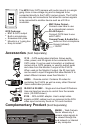
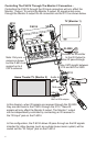
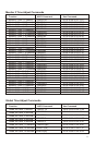
Using The A0505 Remote Control... P-6014 Camera Sequencer
The A0505 is designed to allow you to control the switching functions on your
P-6014. The A0505 allows you to choose any of the 4 cameras or select the
Auto Cycle mode.
Note: Only one
camera connection is
shown in this diagram,
but the P-6014 can
support up to 4 CAT5
cameras.
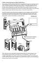
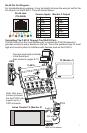
Remote Control Key:
Camera Next... Changes the Monitor output to the next
active camera in the sequence. If you are viewing camera 1,
pressing it once will show camera 2 and so on. Note: Any
unused camera inputs will be skipped.
Camera Cycle... Causes the Monitor output to sequence
through the cameras. The time adjustment on the P-6014 determines
how long each camera view is displayed before switching to the next one.
Note: Any unused camera inputs will be skipped.
1, 2, 3, 4 Camera Views... Changes the Monitor output directly to the
corresponding camera input.
Max CAT5 length between
3112 and 6210 is 250ft.