


Loo
p
Ou
t 1
Loo
p
Ou
t 1
Loo
p O
ut 2
Loo
p O
ut 2
o
Lop
Out 3
o
Lop
Out 3
Ou
Loop t
4Ou
Loop t
4
o
Mo
nitr 1
o
Mo
nitr 1
Mo
n tor 2
i
Mo
n tor 2
i
IR
In (Mon 1
)
IR
In (Mon 1
)
(
o
IR Out M n 2
)
(
o
IR Out M n 2
)
r
Pow
e
r
Pow
e
Inputs
Inputs
Cam
ra 1
e
Cam
ra 1
e
Ca
me
ra 2
Ca
me
ra 2
a 3Ca
me
r
a 3Ca
me
r
Ca
mera 4Ca
mera 4
V
ide
oV
ide
o
Aud
io
Aud
io
O
PR
HA
NN L
C
E
TM
I
O
V SI N
HA
NN L
C
E
I
O
V SI N
TM
M
od
el
014
P-6
Vi
deo
rese
nt
P
Vi
deo
rese
nt
P
Camera
1Camera
1
Cam
era 2
Cam
era 2
C
era
am
3
C
era
am
3
a
C
mer
a 4a
C
mer
a 4
S-232
R
S-232
R
Tm
A ust
i
e
djT m
A ust
i
e
dj
A C
M CERC T5 A ER
A
SEQ
UE
N
ld
Ho
ld
Ho
6
P-6014
TV (Monitor 1)
Home Theater TV (Monitor 2)
6210
3112
IR-3200
Not used
Connect an IR emitter
to the IR Output to
allow IR pass-through.
Video In
2129
BNC to RCA adaptor
Audio In
Max CAT5 length between
3112 and 6210 is 250ft.
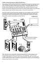
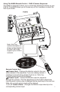
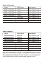
Controlling The P-6014 Through The Monitor 2 Connection...
Controlling the P-6014 through the IR Input connection will only affect the
Monitor 1 output. To control the Monitor 2 output, IR signals must come
through the Monitor 2 output RJ-45 connection via the 3112 as shown below.
In this diagram, when IR signals are received through the IR-2400
they are sent back to the P-6014 through the 3112. These IR
signals will only affect the Monitor 2 output. The Monitor 1 output
can be independently controlled by connecting an IR receiver to
the “IR Input” jack on the P-6014.
In this configuration, the P-6014 allows IR pass through so that IR signals
intended for other devices (such as a whole-house music system) will be
routed out the “IR Output” jack on the P-6014.
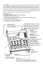
Note: Only one
camera is shown,
but the P-6014 can
support up to 4
CAT5 cameras.
IR-2400
CH
ANEL
O
N V
ISI
N
S
O
U
R
C
E
ZONE
WR
PO E
M
UTE
4
3
2
1
CAM
E
RA
CA
T
V
M
OD
O
V
L
1
2
3
4
MODEL
5
5
A0 0
O
PWER
p
Ou
Loo
t 1
p
Ou
Loo
t 1
L
Ou
t
oop 2L
Ou
t
oop 2
Lop
ut
o O
3Lo p
ut
o O
3
op Ou 4
Lo
top Ou 4
Lo
t
M i
o
1
on t
r
M i
o
1
on t
r
Monito
r 2
Monito
r 2
R
)
I In (
Mo
n 1
R
)
I In (
Mo
n 1
IR ( o
) Ou
t M
n 2IR ( o
) Ou
t M
n 2
ow
er
P
ow
er
P
Inp
utsInp
uts
Ca
mera 1Ca
mera 1
a 2
Camer
a 2
Camer
Cm ra
3
a
e
Cm ra
3
a
e
a
4
Camer
a
4
Camer
V
i odeV
i ode
A i
ud
o
A i
ud
o
O
P
R
C
H
AN
NE
L
TM
I
S
I
ON
V
C
H
AN
NE
L
I
S
I
ON
V
TM
o e
l M d
-
0
1
4
P
6
entVideo Pre
sentVideo Pre
s
Cam
era 1
Cam
era 1
Camera
2Camera
2
Cam
era
3
Cam
era
3
Ca era
4mCa era
4m
S
R -23
2
S
R -23
2
Time Adj
ustTime Adj
ust
CA 5
CAMERA
SE
UENCER
T
Q
old
H
old
H
7
P-6014
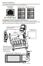
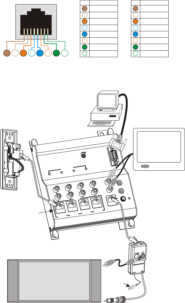
RJ-45 Jack
(TIA 568A)
Camera Inputs
TV (Monitor 1)
Home Theater TV (Monitor 2)
6210
3112
Not used
Video In
2129
BNC to RCA adaptor
Audio In
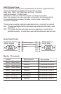
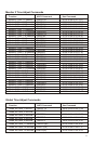
RJ-45 Pin Out Diagram...
For troubleshooting purposes, it may be helpful to know the wire pin out for the
RJ-45 jacks on the P-6014. They are shown below:
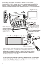
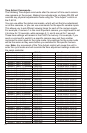
Note: Only one
camera is shown,
but the P-6014 can
support up to 4
CAT5 cameras.
Connect serial data controller
to the Serial port
(Hex codes on pages 8-11)
Controlling The P-6014 Through The RS-232 Port...
The RS-232 port is the most flexible way to control the P-6014 because it
provides access to every feature on the unit. This is the preferred way for most
high-end control system to interface with devices such as the P-6014.
Pin
Signal
Gnd
Video
Gnd
N.C.
Gnd
Audio
Gnd
+12VDC
8
7
6
5
4
3
2
1
Monitor 2 Output
Pin
Signal
Gnd
Video
Gnd
IR
Gnd
Audio
Gnd
+12VDC
8
7
6
5
4
3
2
1
8 7 6 5 4 3 2 11