


3. Setup 11 10/27/2009 1:10 PM
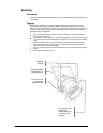
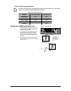
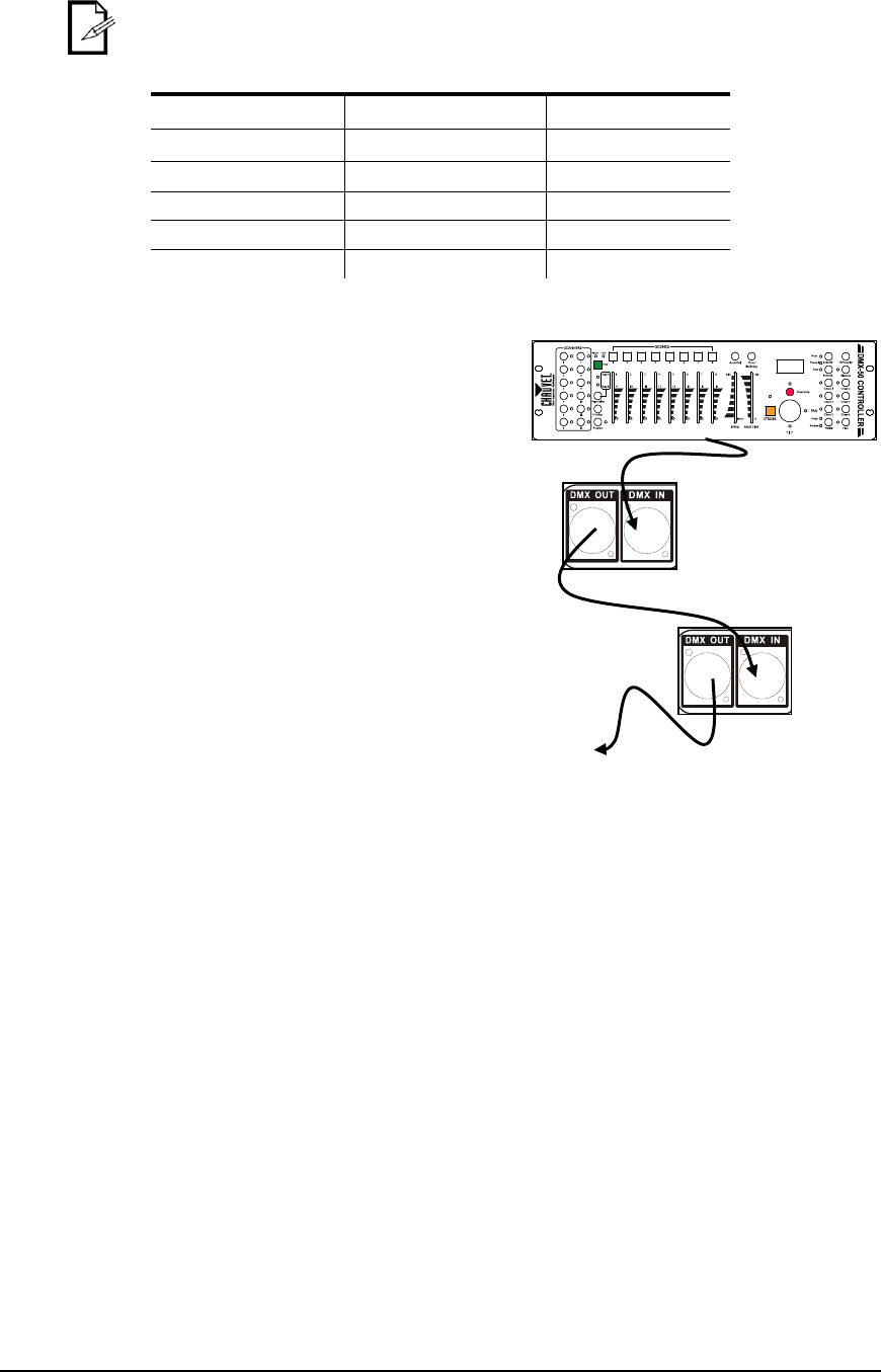
This drawing
provides a general
illustration of the
DMX input/output
panel of a lighting
fixture.
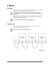
Universal DMX Controller
Continue the link
3-Pin to 5-Pin Conversion Chart
If you use a controller with a 5-pin DMX output connector, you will need to use a 5-pin to 3-pin
adapter. The chart below details a proper cable conversion:
3-PIN TO 5-PIN CONVERSION CHART
Conductor
3-Pin Female (Output)
5-Pin Male (Input)
Ground/Shield
Pin 1
Pin 1
Data ( - ) signal
Pin 2
Pin 2
Data ( + ) signal
Pin 3
Pin 3
Not used
Pin 4
Not used
Pin 5
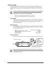
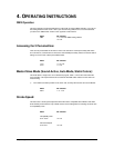
Setting up a DMX Serial Data Link
1. Connect the (male) 3-pin connector side of
the DMX cable to the output (female) 3-pin
connector of the controller.
2. Connect the end of the cable coming from
the controller which will have a (female)
3-pin connector to the input connector of
the next fixture consisting of a (male) 3-pin
connector.
3. Then, proceed to connect from the output
as stated above to the input of the following
fixture and so on.