


4-9
ASA 5505 Getting Started Guide
78-18003-02
Chapter 4 Installing the ASA 5505
Ports and LEDs
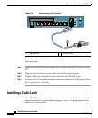
To install a cable lock, perform the following steps:
Step 1 Follow the directions from the manufacturer for attaching the other end of the
cable for securing the adaptive security appliance.
Step 2 Attach the cable lock to the lock slot on the back panel of the ASA 5505.
Ports and LEDs
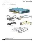
This section describes the front and rear panels of the ASA 5505. This section
includes the following topics:
• Front Panel Components, page 4-9
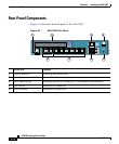
• Rear Panel Components, page 4-12
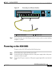
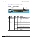
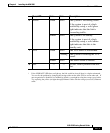
Front Panel Components
The LINK/ACT indicators on the front panel of the ASA 5505 are normally solid
green when a link is established and flashing green when there is network activity.
Each Ethernet interface (numbered 0 through 7) has two LEDs: one to indicate the
operating speed and the other to indicate whether the physical link is established.