


31
SETTING UP
English
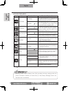
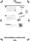
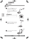
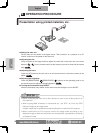
(3) Connecting to the unit with a composite video input terminal equipped.
Connect a commercially available RCA pin plug video cable to the [VIDEO OUT] terminal
on the rear panel.
(
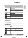
4) Connecting to the PC with a USB cable.
Connect the supplied or commercially available USB cable to the [USB] terminal on the rear
panel.
N o t e
• We recommend using a USB 2.0 compliant USB cable.
•
If you plug into a USB connector with the power on, the PC may not recognize this device.
• Depending on the USB environment used by the PC or peripheral equipment using
the USB 2.0 compliant cable, image transfer may be disrupted.
•
Operation is not guaranteed for all environments.
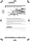
N o t e
• Only one image can be output at a time; either [RGB OUT] or [VIDEO OUT]. For more
information on switching the image output, refer to "RGB/Video Switch".
P.15
• To protect the unit and peripheral devices, unplug the power plug and the AC
adapter, and turn off all other devices before connecting the video cable.
•
When plugging in or unplugging the power plug, the AC adapter, or video cable, hold the plug
of the cable.
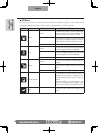
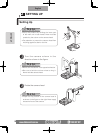
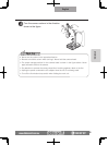
(5) Connecting the AC adapter.
Connect the DC plug of the supplied AC adapter to the [DC IN 12V] terminal on the rear
panel before inserting the AC adapter in an outlet.
n
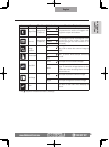
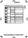
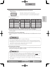
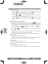
Specifications of the analog RGB input terminal of this product.
Signal allocation
10
9 8 7 6
5 4 3 2 1
15 14 13
DSUB 15P shrink terminal (Female)
12 11
Video signal: Analog 0.7V (p-p) with 75Ω terminated
Horizontal synchronized signal: TTL level (Positive/negative polarity)
Vertical synchronized signal: TTL level (Positive/negative polarity)
Pin assignment
Pin No. Name Pin No. Name Pin No. Name
1
Video signal (Red)
6 GND (Red) 11 GND
2
Video signal (Green)
7 GND (Green) 12 N.C
3
Video signal (Blue)
8 GND (Blue) 13
Horizontal syn-
chronized signal
4 N.C 9 N.C 14
Vertical synchro-
nized signal
5 GND 10 GND 15 N.C