


560H Series Connector Conforming to Ver. 4
11
Dimensions are in millimeters (inches) www.fcai.fujitsu.com
Specifications
subject to change
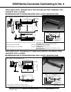
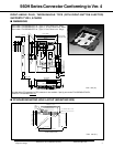
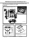
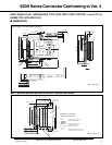
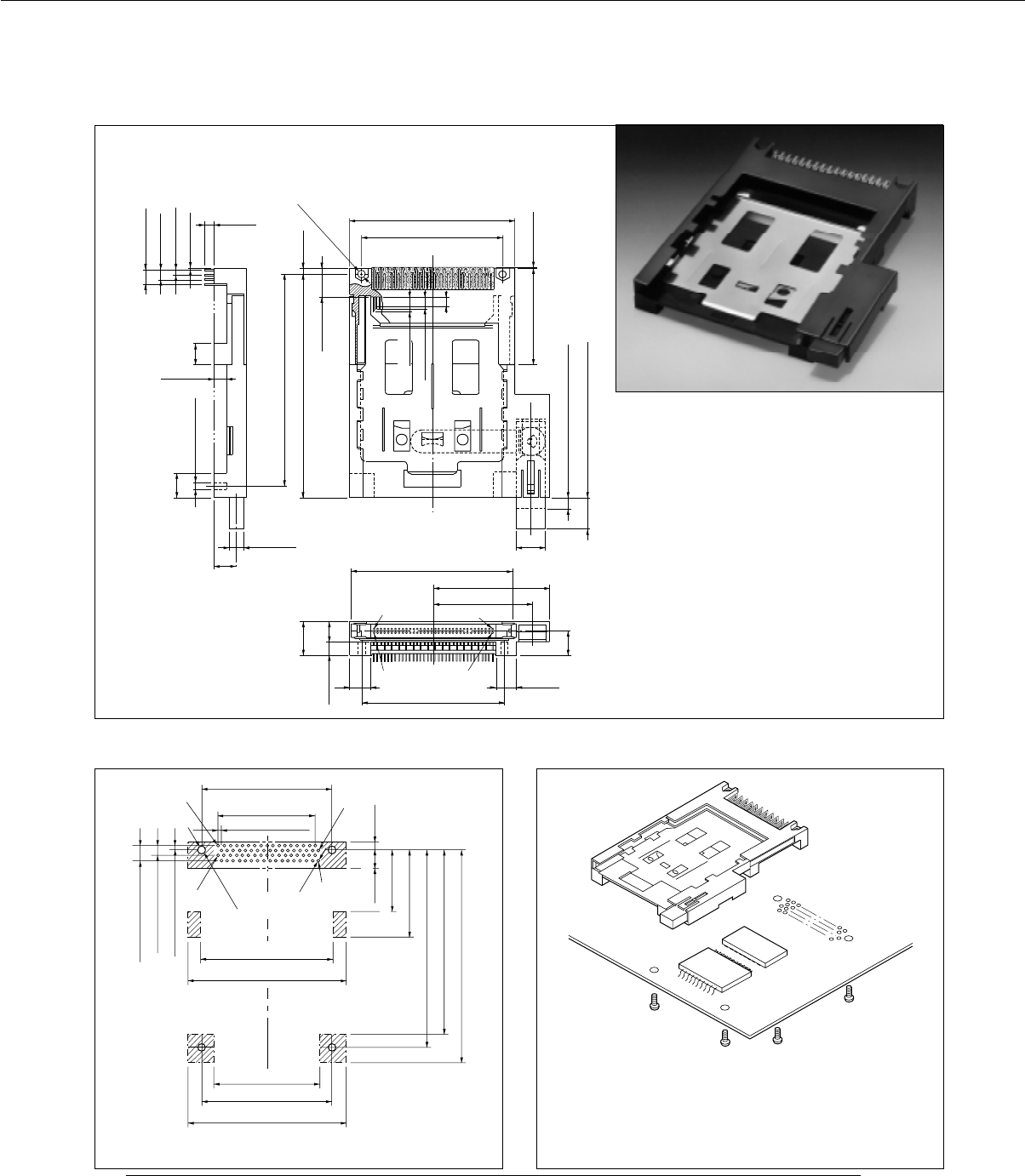
RIGHT-ANGLE PLUG, THROUGHHOLE TYPE (WITH RIGHT-BUTTON EJECTOR, 4.5 MM
(0.177 IN.) RAISED TYPE) SUPPORTS TYPE I, II CARDS
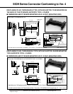
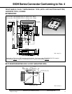
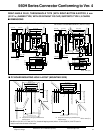
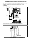
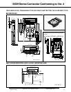
■ DIMENSIONS
Part number: FCN-565P068-G/J25-V4 (supports type I, II card)
Part number: FCN-565P068-G/J25-4V (supports type I, II, III card)
3(0.118)
0.51 (0.020)
1.905 (0.075)
3.810 (0.15)
5.715 (0.225)
8
(0.315)
4.5 (0.177)
9 (0.354)
4.8 (0.189)
8 (0.315)
2.42
(0.095)
11.2 (0.441)
2- ø 2.2 (0.087)
76.48 (3.011)
81.88 (3.224)
59.7 (2.35)
50.8 (2)
0.2 (0.0078)35.2 (1.386)
4.25 (0.167)
3.5
(0.138)
5.2 (0.205)
10 (0.394)
When a card is inserted
12.5 (0.492)
42 (1.654)
35.5 (1.398)
4.5 (0.177)
59 (2.323)
No.68
No.35
No.1
No.34
11.5 (0.453)
7
(0.276)
50.8 (2)
8.5 (0.335)
8 (0.315)
ø 2.2 , 4.5 deep
When a card is ejected
5 (0.197)
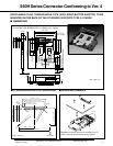
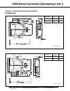
■
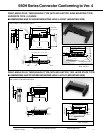
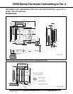
PC BOARD MOUNTING HOLE LAYOUT (MOUNTING SIDE)
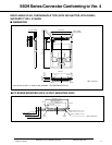
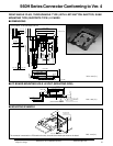
■ MOUNTING EXAMPLE
±0.1 (0.0039)
5.715 (0.225)
±0.05 (0.0020)
3.810 (0.15)
±0.05 (0.0020)
1.905 (0.075)
±0.05 (0.0020)
50.8 (2)
±0.1 (0.0039)
1.27 (0.05)
±0.05 (0.0020)
1.27 (0.05) × (68/2-1)
= 41.91 (1.65)
No.1
No.34
No.35
No.68
3.42 (0.135)
–0
–0
+0
33.78 (1.330)
–0
76.48 (3.011)
±0.1
71.88 (2.830)
+0
82.88 (3.263)
–0
51.7 (2.035)
+0
61.7 (2.429)
–0
41.7 (1.642)
+0
50.8 (2)
±0.1 (0.0039)
61.7 (2.429)
–0
±0.1 (0.0039)
±0.05 (0.0020)
6.58 (0.259)
23.78 (0.936)
4 - ø 2.8 (0.110)
68- ø 1 (0.0394)
Unit: mm (in.)
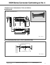
Component mounting is prohibited in the hatched areas.
• Components with a height of 4.3 mm (0.169 in.) maximum can
be installed under the connector.
• Use M2.5 mm (0.098 in.) x 5 mm (0.197in.) self-tapping screws
(when a 1.6 mm (0.063 in.) thick PC board is used) to mount
the connector to the board.
Unit: mm (in.)