


Chapter 2 System Features and Capabilities 2-3
For more information on CPU operational modes, refer to the SPARC Enterprise
M3000/M4000/M5000/M8000/M9000 Servers XSCF User’s Guide.
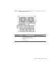
2.1.2 Memory Subsystem
Each memory board in the server contains four or eight DIMMs (dual inline memory
modules). Both midrange servers use Double Data Rate II (DDR II) type DIMMs. The
memory subsystem supports up to eight-way memory interleaving for high-speed
memory access. For more information on memory boards and DIMMs, see
Section 1.3.3, “Memory Board” on page 1-13.
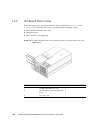
2.1.3 I/O Subsystem
Each I/O subsystem contains the following :
■ PCI cards—Four short PCI Express (PCIe) slots (four upper slots) and one short
PCI-X slot (lowest slot). For additional information see
FIGURE 1-18 andFIGURE 1-19 .
■ One I/O controller (IOC) chip, which is the bridge chip between the system bus
and the IO bus
■ PCI-Express switches or bridges connected to the slots
The PCI slots support the hot-plug function, which enables you to replace the IOU
while the domain is operating. Before you can remove a PCI card, you must first
unconfigure and disconnect it.
You can also add an optional External I/O Expansion Unit, which contains additional
PCI Express slots or PCI-X slots.
2.1.4 System Bus
The CPU, memory subsystem, and I/O subsystem are directly connected to implement
data transfer by using a high-speed broadband switch. Individual components are
connected through tightly coupled switches, which use an even latency for data
transfer. These components can be added to the server to enhance the processing
capability (in proportion to the number of components added).
When a data error is detected in a CPU, Memory Access Controller (MAC), or I/O
Controller (IOC), the system bus agent corrects the data and transfers it.