


308924 3
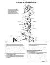
Turbine Kit Installation
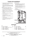
Fig. 3
107 (31)
104 (25)
(1)
109 (83)
7943B
105 (41)
108 (82)
102 (24)
106 (19)
103 (42)
(7)
(27)
(2)
(18)
(5)
(23)
(33)
(34)
(6)
(48)
One- and two-digit numbers
(in parentheses) refer to parts
as they are called out in
manual 308808. Three-digit
numbers refer to new kit parts.
4. Remove turbine gasket (25), three screws (6),
turbine plate (82), and three turbine spacers (83).
NOTE: Steps 5 and 8 apply only if your GTS-4900
turbine sprayer has a speed controller (48). Installation
of this 2-Speed Turbine Conversion Kit does not
include reconnecting wires to the speed controller.
The speed controller is no longer used with the
2-speed turbine.
5. Remove turbine motor wires from spade terminals
on speed controller (48).
6. Rotate turbine (24) from outlet fitting (18) and lift
up from turbine spacers (23) and turbine duct (5)
to remove.
7. Remove rocker switch (31) and wires connected to
it (Fig. 4 wiring diagram).
8. Remove two remaining wires connecting speed
controller (48) to red rocker switch (34) and filter
indicator light (33).
Rocker Switch Installation and Wiring
See Wiring Diagram in Fig. 4.
1. In orientation shown in Fig. 3, install rocker switch
(107) in hole left by removed switch (31).
2. Connect male tab end of one white wire (110) to
spade terminal 2 of switch (107). Position spade to
outside of switch to ease connection of second
wire. Connect other end of white wire to spade
terminal 5 of red rocker switch (34).