


z
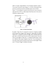
IM-30/IM-100 offers 2 input ports; designated as Input Port 0
nd Input Port 1. Both ports are TTL level. The input ports are accessed
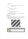
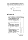
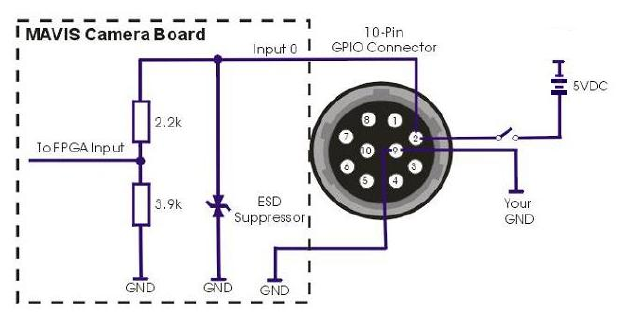
typical circuit that you can use to input a
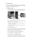
1.4.7 Input/Output
Input Ports
The MAVIS
a
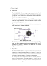
via the 10-pin circular connectors on the back of the camera. Please refer
Table 2-1 for input port pin assignments.
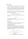
For each port, an input voltage between 0.0 and 1.5VDC indicates a logical
0. An input voltage between 3.5 and 5.0 VDC indicates a logical 1. Typical
current draw for the input
port is 1mA.
Figure 1-6 is an example of a
signal into the MAVIS IM-30/IM-100 cameras.
Figure 1-9: Typical Input Circuit
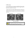
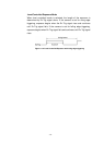
By default, Input Port 0 is assigned to receive an external trigger (Ex-Trig)
signal that can be used to control the start of exposure. Also you can
change the Ex-Trig signal to Input Port 1 and please refer “5.6 External
Trigger” for detail information.
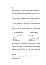
z Output Ports
The MAVIS IM-30/IM-100 offers 4 output ports; designated as Output Port 0,
Output Port 1, Output Port 2 and Output Port 3, all are TTL level. The
output ports are accessed via the 10-pin circular connectors on the back of
the camera. Please refer Table 2-1 for input port pin assignments.
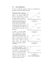
For each port, an output voltage between 0.0 and 0.44VDC indicates a
logical 0. The maximum low level output voltage (i.e., 0.44VDC) will be
present when the driver is sinking the maximum allowed input current of
- 13 -