


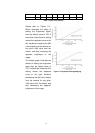
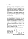

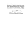
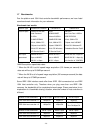

24mA. An output voltage between 4.2 and 5.0VDC indicates a logical 1.
output voltage (i.e., 4.2VDC) will be present when
rcing the maximum allowed output current of 24mA.
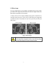
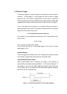
an example of a typical circuit that you can use to monitor an
output port with a LED or an Opto-coupler. Note that current in the circuit is
The minimum high level
the driver is sou
Figure 1-7 is
limited by an external resistor.
Figure 1-10: Typical Output Signal
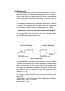
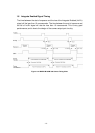
By default, Output Port 0 is assigned to transmit an integration enabled
(Int-En) signal that indicates when exposure is taking place. By default,
Output Port 1 is assigned to transmit a trigger ready (Trig-Rdy) signal that
goes high to indicate the earliest point at which exposure start for the next
frame can be triggered. Please refer “1.6 Integrate Enabled Signal Timing”
for a detailed camera signal integrate timing chart. The pin assignment of
the camera output sig can be changed. Please
nals to physical output ports
refer “5.7 External Trigger” for detailed information.
- 14 -