


8
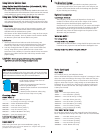
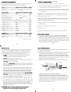
IInnssttaalllliinngg tthhee GGeeaarr SSlleeeevvee
It is easiest to install the gear
sleeve and port with the
housing laying on it’s back with
the camera lens pointing up.
Position the clear plastic Gear
Sleeve with the gear teeth
pointed toward the housing.
The Gear Sleeve slides over the
lens and the Gear Sleeve’s ribs
slide into the grooves on the extended ears of the Zoom Clamp.
The gear teeth on the Gear Sleeve should mesh with the drive
gear in the port opening on the housing. (See front view
of housing)
IInnssttaalllliinngg tthhee PPoorrtt
There are two port locks on
the front of the housing.
(See housing front) Each
port lock has a Release
Button, lift the release
button and slide each Port
Lock away from the port
opening. In the unlocked
position the Release Button
will remain in the up
position as shown.
Gear Sleeve
Rib
Gear
Teeth
Port Lock
Release
Button
Lift Release
Button to
Unlock
Locked Position
6
C
C
l
l
o
o
s
s
i
i
n
n
g
g
t
t
h
h
e
e
H
H
o
o
u
u
s
s
i
i
n
n
g
g
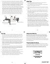
1. Place housing face down in your lap.
2
. Check to see that there is an
o-ring on the housing back and
that it is clean and in its proper
location.
3
. Guide the back onto the housing.
The o-ring should touch the
housing all the way around.
There should be an even gap all
the way around between the
housing and the housing back.
4. Lift the lid snaps so they are
extended and place the lid
snap into the hook on the
housing back.
5. To close the housing push
down on the lid snaps until
they snap into place . Lid
snaps on opposite sides of the
housing should be closed at the
same time. Be sure they are
down far enough to engage
the lock.
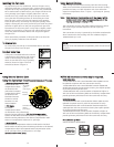
DDoouubbllee cchheecckk
- Once the housing is closed, check the o-ring seal.
Check the gap between the housing back and the housing, it
should be even all the way around.
Look through the clear plastic back at the o-ring. You should see
a darkened area where the o-ring is compressed against the
housing back. If you do not see an even black compression seal
all the way around the back, open the lid snaps, reseat the
housing back and close the lid snaps. Visually check the seal again.
o-ring
housing back
housing back
housing
housing
o-ring
even gap
all 4 sides
7
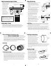
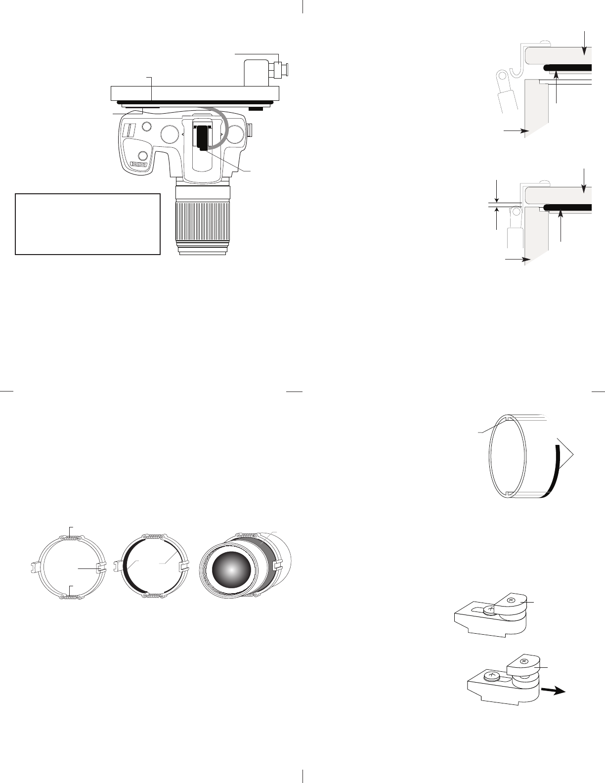
Springs
Groove
Rubber Strips
Lens Zoom Grip
Springs
N
N
O
O
T
T
E
E
:
:
H
H
o
o
u
u
s
s
i
i
n
n
g
g
E
E
x
x
p
p
o
o
s
s
u
u
r
r
e
e
C
C
o
o
m
m
p
p
e
e
n
n
s
s
a
a
t
t
i
i
o
o
n
n
C
C
o
o
n
n
t
t
r
r
o
o
l
l
The housing’s
E
E
x
x
p
p
o
o
s
s
u
u
r
r
e
e
C
C
o
o
m
m
p
p
e
e
n
n
s
s
a
a
t
t
i
i
o
o
n
n
C
C
o
o
n
n
t
t
r
r
o
o
l
l
is notched and
spring loaded. Pull out on the control to rotate. The spring loaded
control will depress the Exposure Compensation Button on the
camera while you turn the camera’s Control Dial to set the
desired compensation. Once the desired compensation has been
selected pull out on the control and rotate so it is not in contact
with the camera’s Compensation Button.
Z
Z
o
o
o
o
m
m
C
C
l
l
a
a
m
m
p
p
I
I
n
n
s
s
t
t
a
a
l
l
l
l
i
i
n
n
g
g
t
t
h
h
e
e
Z
Z
o
o
o
o
m
m
C
C
l
l
a
a
m
m
p
p
The two halves of the Zoom Clamp are held together by springs.
This allows the Zoom Clamp to be stretched to fit over the zoom
grip on different diameter lenses. The Zoom Clamp should fit
tight around the lenses zoom grip so that it does not slip when
using it to rotate the camera’s zoom ring. If the Clamp is loose,
adhere the thin black rubber strips to the inside of each half of
the Zoom Clamp as shown above. The Zoom Clamp has two
extended ears with grooves. These grooves accept the Ribs on
Gear Sleeve.
5
F
F
l
l
a
a
s
s
h
h
C
C
o
o
n
n
n
n
e
e
c
c
t
t
i
i
o
o
n
n
f
f
o
o
r
r
E
E
x
x
t
t
e
e
r
r
n
n
a
a
l
l
S
S
t
t
r
r
o
o
b
b
e
e
s
s
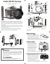
When using an external strobe connect the housings Hot Shoe
Connector, slide the
connector into the
hot shoe of the
camera from the
b
ack of the camera
as shown. Slide
the connector
forward until
i
t stops. This
should be done
before the camera
is secured with the
mounting bolt.
I
I
n
n
s
s
t
t
a
a
l
l
l
l
i
i
n
n
g
g
C
C
a
a
m
m
e
e
r
r
a
a
i
i
n
n
H
H
o
o
u
u
s
s
i
i
n
n
g
g
Before installing the camera, pull out on the controls in the
front section of the housing. This will allow the camera to slide
in easier. Once the camera is installed and the lid snaps have
been closed, return the controls to their operating position.
ww
w
w
w
w
ww
ww
ww
w
w
ww
w
w
ww
w
w
w
w
w
w
ww
w
w
ww
ww
ww
ww
w
w
ww
ww
ww
w
w
w
w
w
w
w
w
ww
w
w
w
w
w
w
ww
ww
ww
ww
ww
ww
ww
ww
w
w
ww
ww
ww
ww
ww
w
w
ww
ww
w
w
ww
w
w
w
w
ww
ww
Camera
H
ot Shoe
C
onnector
External Strobe Connector
W
aterproof Cap
O-ring
Strobe ID
Switch
Housing Back
C
C
a
a
u
u
t
t
i
i
o
o
n
n
:
:
Do not remove the External
Strobe Connector’s waterproof
cap unless an external sync cord
is going to be plugged in.