


10
3. Do not heat a part with a flame to free it for removal unless
the part being heated is already worn or damaged beyond
repair and no additional damage will occur to other parts.
In general, the hoist is designed to permit easy disassembly
and assembly. The use of heat or excessive force should
not be required.
4. Keep the work area as clean as practical, to prevent dirt and
other foreign matter from getting into bearings or other
moving parts.
5. When grasping a part in a vise, always use leather-covered
or copper-covered vise jaws to protect the surface of the
part and help prevent distortion. This is particularly true of
threaded members, machined surfaces and housings.
6. Do not remove any part which is press fit in or on a
subassembly unless the removal of that part is necessary for
repairs or replacement.
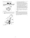
Disassembly
Brake Disc Replacement
1. Unscrew U-nuts (36). Remove wheel cover (35).
2. Remove hand chain (46) from hand wheel (31).
3. Remove cotter pin (34), unscrew pinion nut (33) and
remove washer (32).
4. Remove hand wheel (31) by holding the load chain (43)
and rotating hand wheel (31) counterclockwise until it can
be lifted off pinion shaft (13).
5. Remove brake cover (30) and brake disc A (27).
6. Remove ratchet gear (29) and brake disc B (28).
Cleaning, Inspection and Repair
Use the following procedures to clean and inspect the
components of the hoist.
Cleaning
Clean all hoist component parts in an acid free solvent (except
for the brake disc). The use of a stiff bristle brush will facilitate
the removal of accumulated dirt and sediments on the gears and
frames. Dry each part using low pressure, filtered compressed air.
Inspection
All disassembled parts should be inspected to determine their
fitness for continued use. Pay particular attention to the
following:
1. Inspect all gears for worn, cracked, or broken teeth.
2. Inspect shafts for ridges caused by wear. If ridges caused
by wear are apparent on shafts, replace the shaft.
3. Inspect all threaded items and replace those having
damaged threads.
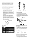
4. Measure the thickness of the brake discs. If brake discs do
not have uniform thickness or are less than 5/64 in. (2 mm)
thick replace brake discs.
Repair
Actual repairs are limited to the removal of small burrs and
other minor surface imperfections from gears and shafts. Use a
fine stone or emery cloth for this work.
1. Worn or damaged parts must be replaced. Refer to the
applicable parts listing for specific replacement parts
information.
2. Inspect all remaining parts for evidence of damage.
Replace or repair any part which is in questionable
condition. The cost of the part is often minor in comparison
with the cost of redoing the job.
3. Smooth out all nicks, burrs, or galled spots on shafts,
bores, pins, and bushings.
4. Examine all gear teeth carefully, and remove nicks and
burrs.
5. Polish the edges of all shaft shoulders to remove small
nicks which may have been caused during handling.
6. Remove all nicks and burrs caused by lockwashers.
Assembly
CAUTION
• The brake will not operate properly if there is too much oil
on the brake discs (27 and 28). Excessive oil or grease on
brake components could cause the load to slip.
1. Dip replacement brake discs (27 and 28) in ISO VG32
hydraulic oil or SAE 10 oil for two seconds. Wipe off
excess oil.
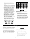
2. Place brake disc B (28) over hub (26). Brake disc B (28)
has a smaller outside diameter than brake disc A (27).
3. Install ratchet gear (29) on hub (26) so recessed face fits
over brake disc B. Teeth of ratchet gear (29) must engage
pawl (24). Ratchet gear (29) should not rotate
counterclockwise and should “click” when rotating
clockwise.
4. Place brake disc A (27) on ratchet gear (29).
5. Place brake cover (30) over stay bolts on side plate 1
assembly (1).
6. With brake surface of handwheel (31) towards the brake
disc A (27), place handwheel (31) on pinion shaft (13).
Rotate handwheel (31) clockwise until clicking occurs.
Hold load chain (43) if necessary.
7. Place washer (32) over pinion (13). Install pinion nut (33)
and cotter pin (34). Refer to “Brake Adjustment.”
8. Install hand chain (42) on handwheel (31). Make sure hand
chain (42) is seated properly.
9. Place wheel cover (35) over stay bolts. Install U-nuts (36).
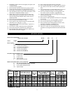
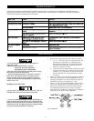
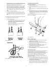
Gears (14)
1/2, 1 and 2 ton units do not use gears with a circle.
On 1-1/2, 3 and 5 ton units, each hoist body must have one gear
without a “circle” and one gear with a “circle”. Refer to Dwg.
MHP0044.
(Dwg. MHP0044)
NOTICE
• The 1/2 ton hoist has a center pinion gear with only 5 teeth.