


9
4. Run the new chain to its anchor point. On smaller units, use
the hand chain (42) to move the load chain. On larger units,
load chain (43) installation can be speeded up by
unscrewing U-nuts (36), removing gear cover (17), support
plate (16) and taking out 2nd gear set (14). With the 2nd
gear set (14) removed, the load chain (43) can be pulled by
hand through the hoist body and hook blocks. Reinstall 2nd
gear set, support plate (16), gear cover (17) and U-nuts
(36).
5. Remove “C” link and old chain.
6. On 1/2 to 2 ton hoists, anchor load chain (47) to bottom
hook block. On 3 and 5 ton units, anchor load chain to top
hook frame. To connect, install chain bolt (39) and U-nut
(40).
For information on connecting unloaded end of load chain refer
to “Attaching End of Load Chain” section.
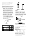
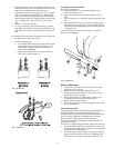
7. Check for the following:
a. The load chain did not become twisted, when reeving
the load chain (43) between the idler sheave on the
bottom hook assembly and the hoist load sheave.
Refer to Dwg. MHP0020.
b. Make sure load chain (43) is reeved between load
sheave (6) and chain guides (7).
(Dwg. MHP0020)
(Dwg. MHP0043)
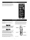
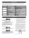
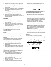
Attaching End of Load Chain
Refer to Dwg. MHP0410
1. Push end pin (20) “in”, towards end spring (19) and
remove end anchor A (21).
2. Slide end link of load chain (43) on end anchor A (21)
shaft.
3. Insert end anchor A (21) shaft into end anchor B (22) guide
hole.
4. Reinstall end anchor A (21) on end pin (20). Depress and
align end pin (20) in side plate 1 (1) hole. When released
end pin (20) should spring into position and slide into hole
in side plate 1 (1).
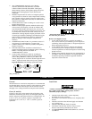
Ensure load chain (43) is not twisted, kinked or “capsized.”
Refer to Dwg. MHP0043.
20
21
22
19
(Dwg. MHP0410)
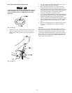
Brake Adjustment
1. Unscrew nuts (36) and remove wheel cover (35) so that
handwheel (31) is exposed.
2. Remove cotter pin (34) and tighten pinion nut (33)
(Clockwise). Hold load chain (47), if necessary, to keep
pinion shaft (13) from rotating.
3. Back off pinion nut (33) approximately 1/8th of a turn
(Counterclockwise) and reinsert cotter pin (34).
4. Remove all slack from the chain.
5. Pull on the hand chain to lift the load approximately 2 feet
(0.5 m) off the floor.
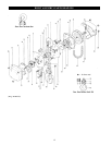
General Disassembly
The following instructions provide the necessary information to
disassemble, inspect, repair, and assemble the hoist. Parts
drawings of the hoist assembly are provided in the Parts Section.
If a hoist is being completely disassembled for any reason,
follow the order of the topics as they are presented.
It is recommended that all maintenance work on the hoist be
performed on a bench.
In the process of disassembling the hoist, observe the following:
1. Never disassemble the hoist any further than is necessary to
accomplish the needed repair. A good part can be damaged
during the course of disassembly.
2. Never use excessive force when removing parts. Tapping
gently around the perimeter of a cover or housing with a
soft hammer, for example, is sufficient to break the seal.