Document 900.0345 Rev 1.02 9
03/07
Connect the Power Cable
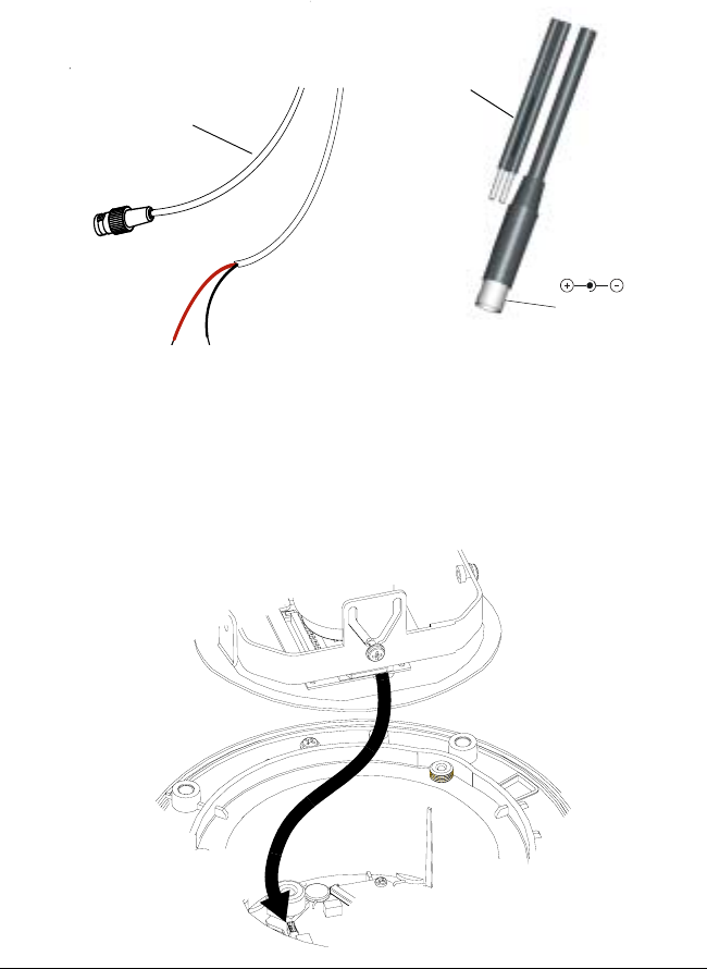
1. Follow Figure 4 for the wiring connection.
Figure 4 Wiring
2. Connect the power/video cable from the gimbal assembly to the camera
board (see Figure 5).
Note For secure installations, surface-mounted cables should be
protected by plastic or metal cable covers.
Figure 5 Power Cable Connection
Coaxial Cables UTP Cables
Video: Unshielded
Twisted Pair wire
Video: female BNC
Power
red +
connect to red +
black -
connect to ground
Power: 2.1 mm
male jack center pin
Gimbal assembly
Camera board
Power/video cable


