


Tech Note
2
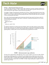
Displaying a high dynamic range image on a standard monitor will require mapping the output to t the
monitor’s dynamic range capability. For the image described above, start by creating a 20-bit image map
using the raw pixel data. Then create a 10-bit image map to display on the monitor by dividing the 20-bit im-
age map by 1024. Or create a 12-bit image map by dividing the 20-bit image map by 512.
The preceding process describes using both output channels in 10-bit mode. Alternatively you can use the
8-bit output from both channels to create a 16-bit HDR image. To do this, use the same method as described
above, only calibrate the 2 sensors so that Sensor B = Sensor A * 256. This reduces the total dynamic range,
but increases the precision of output values in the upper half of the range.
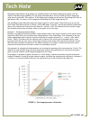
Example 2 - Overlapping Dynamic Range
Example 1 provides the maximum dynamic range possible using 10-bit output. However, there may be issues
around the 1023/1024 count transition that cause problems in the fused image. This is because of the fast
shutter speed being used on Sensor B and the relatively low output precision (i.e., 1 count = 1024 while 2
counts = 2048). This means that the inherent noise in Sensor B has a much more noticeable effect, caus-
ing some pixels that are very close in actual light intensity to be output with dramatically different values.
While this type of impact is expected in the darkest portions of an image, its effect on luminance values
around the transition point can result in some very noticeable artifacts.
One approach for mitigating this phenomenon is to overlap the responses of the two sensors by 2-4 bits. This
reduces the total dynamic range, but also signicantly reduces the amplication of noise at the transition
point to provide a better overall image throughout the full range.
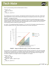
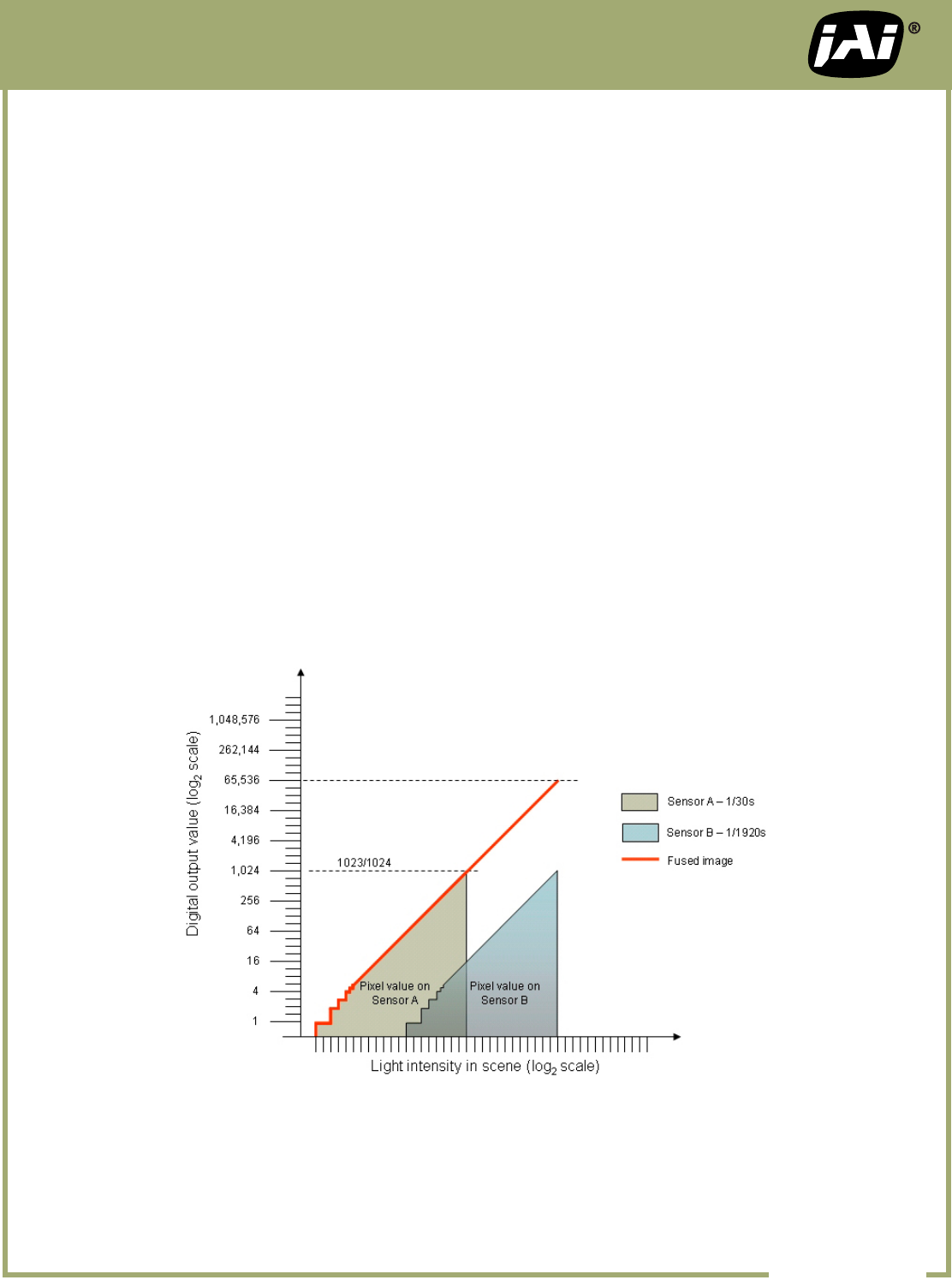
For example, to produce a cleaner transition in a 16-bit image, calibrate the sensors using the process de-
scribed in Example 1 (using 10-bits per channel output), but make the transition point 64 counts, so Sensor B
= Sensor A * 64. Now the 4 MSB of Sensor A will overlap with the 4 LSB of Sensor B (see Figure 4).
FIGURE 4 – Overlapping sensor calibration
NO. TN-0902 pg 3