


Tech Note
2
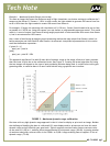
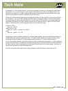
Now as Sensor A approaches its saturation point (512 – 1023 counts) the output uses the average of both sen-
sors’ data to “smooth” the transition between the two sensor response graphs (see Figure 6). It still limits
the use of the lowest bits on Sensor B (those that are most susceptible to noise) and keeps the calibration
factor at 64 to increase the output precision of the upper bits.
FIGURE 6 – Averaging used to smooth calibration in overlapped region
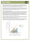
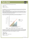
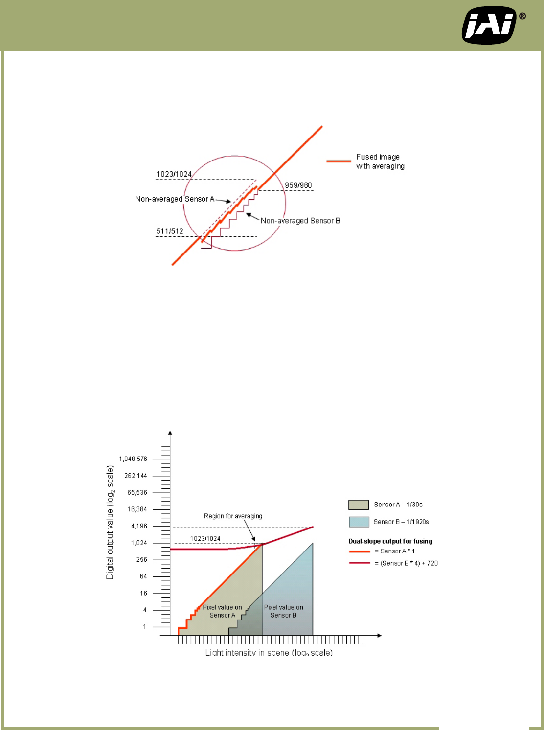
Example 4 – Dual-Slope Dynamic Range
Lastly, you can use the approach described in Example 3 to smooth the transition between two sensor output
lines that have intentionally been given different slopes. This dual-slope arrangement can be used to com-
press or expand the dynamic range in a particular region of the luminance values -- similar to a look-up
table, but over an expanded dynamic range as shown in Figure 7.
To use this approach, overlap and calibrate the two sensor responses as in Example 2, as if a post-processing
factor of 64 was going to be applied to the value of Sensor B. However, during post processing, apply a
smaller multiplier for Sensor B, combined with a specic offset value, to create a “atter” output line that
intersects the output from Sensor A somewhere in the uppermost bit of its output graph.
FIGURE 7 – Dual-slope HDR calibration
NO. TN-0902 pg 5