


- 4 -
CV-M50
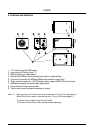
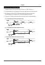
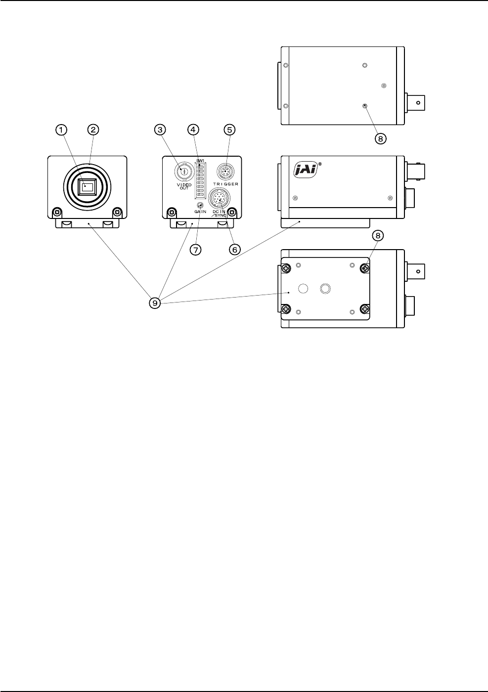
4. Locations and Functions
1 1/2" interline transfer CCD sensor.
2 Lens mount of C-mount type. *1)
3 BNC connector for video output.
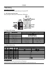
4 Switch block SW1 for shutter speed and function modes setting.
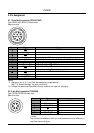
5 6-pin multi connector for WEN and EEN output external trigger input.
6 12-pin multi connector for +12V DC power, video output and HD/VD input/output.
7 GAIN potentiometer for manual gain adjustment.
8 Screw holes for Tripod mount plate.
9 Tripod mount plate to place the camera on tripod.
Note: *1) Rear protrusion on C-mount lens must be less than 10.0 mm (0.4 inches approx.).
When IR-cut filter is used, it must be less than 7.0 mm (0.28 inches approx.).
The IR cut filter is placed in the C-mount thread.
The C-mount 25 mm IR cut filter must be ordered separately.