


EN 41
erty
i
EWRT
Y
w
p
Q
u
O
U
I
o
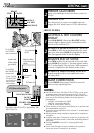
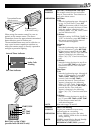
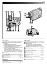
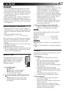
Connectors
w J terminal (JLIP (Joint Level Interface Protocol)
Connector.)
(Located beneath the jack cover)
•Connect the Editing Cable when performing
Random Assemble Editing (੬ pg. 32).
•It is used to connect the camcorder to a device
such as a personal computer.
For further detail consult your nearest JVC
dealer. Information (in English) is also available
at our home page: http://www.jvc-victor.co.jp/
e DC IN Jack......................................... ੬ pg. 5
The jacks
r
to
y
are located beneath the jack cover.
r VIDEO OUT Jack............................... ੬ pg. 27
t RF DC OUT Jack................................ ੬ pg. 27
y AUDIO OUT Jack.............................. ੬ pg. 27
Indicators
u Tally Lamp ......................................... ੬ pg. 10
i Power On Indicator ........................... ੬ pg. 10
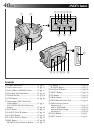
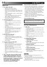
Other Parts
o Video Light (GR-AX470 only)..............੬ pg. 13
p •Camera sensor
Be careful not to cover this area; built-in
here is the sensor necessary for shooting.
•Remote sensor (GR-AX470 only)...... ੬ pg. 35
Q Microphone ....................................... ੬ pg. 37
W Shoulder Strap Eyelets........................ ੬ pg. 9
E Clock Battery Compartment................੬ pg. 6
R Battery Pack Mount ........................... ੬ pg. 4
T Electronic Viewfinder......................... ੬ pg. 6
Y LENS COVER Switch ......................... ੬ pg. 10
U Grip Strap .......................................... ੬ pg. 9
I VIDEO LIGHT ON/AUTO/OFF Switch
(GR-AX470 only) ............................... ੬ pg. 13
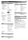
O Tripod Mounting Socket ......................੬ pg. 9