


EN87
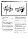
Controls
1 PRINT Button
Enables printing using the optional printer
equipped with a PRINT DATA connector. Refer to
the separate “FOR OWNERS OF AN OPTIONAL
PRINTER” instruction sheet.
2 PRINT FRAME Button .......................... ੬ pg. 51
3 E-MAIL CLIP REC Button ...................... ੬ pg. 44
4 START/STOP Button ............................. ੬ pg. 16
5 •Power Zoom Lever [T/W] .................. ੬ pg. 20
•Speaker/Headphone Volume Control
[VOL.] .............................................. ੬ pg. 40
6 •MENU Wheel [+, –,
4
] ..................... ੬ pg. 26
•LCD Monitor Brightness
Control [+, –] .................................... ੬ pg. 16
7 Snapshot Button
[SNAPSHOT]................੬ pg. 18, 19, 22, 24, 65
8 INDEX Button .......................... ੬ pg. 37, 46, 47
9 IMAGE SIZE/RES. Button ...................... ੬ pg. 13
0 DIGITAL SOUND Button ............... ੬ pg. 37, 77
! Battery Release Switch
[BATT. RELEASE].................................... ੬ pg. 7
@ OPEN/EJECT Switch ............................. ੬ pg. 10
# •Play/Pause Button [
4
/6] ................... ੬ pg. 40
•EXPOSURE Button ............................ ੬ pg. 38
$ •Rewind Button [
2
] ......................... ੬ pg. 40
•BACKLIGHT Button .......................... ੬ pg. 38
% Stop Button [5] ................................... ੬ pg. 40
^ •Fast-Forward Button [
3
] ................. ੬ pg. 40
•FOCUS Button .................................. ੬ pg. 25
& Operation Switch [ , ] .................. ੬ pg. 14
* POWER Switch
[ , ,
M
E
M
O
R
Y
P
L
A
Y
, OFF] ............ ੬ pg. 14
( Lock Button ......................................... ੬ pg. 14
) MODE Dial
[ , VIDEO,
DUAL
, ] .................. ੬ pg. 15
q Dioptre Adjustment Control ................... ੬ pg. 8
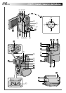
Connectors
The connectors w to r are located beneath a cover.
w Digital Video Connector
[DV IN/OUT: GR-DVX10,
DV OUT: GR-DVX9]
(i.link*) .............................. ੬ pg. 58, 59, 62, 63
* i.Link refers to the IEEE1394-1995 industry
specification and extensions thereof. The logo
is used for products compliant with the i.Link
standard.
e •Audio/Video Output Connector
[AV OUT] ......................................... ੬ pg. 56
•Headphone Connector [ ]............... ੬ pg. 76
r Multi Connector
When attached to the Docking Station, this part is
connected.
Indicators
t Tally Lamp........................................... ੬ pg. 16
y POWER Lamp ..................................... ੬ pg. 16
Other Parts
u LCD Monitor ................................. ੬ pg. 16, 17
i Battery Pack Mount ............................... ੬ pg. 7
o Speaker ............................................... ੬ pg. 40
p Camera Sensor
Be careful not to cover this area, a sensor
necessary for shooting is built-in here.
Q Stereo Microphone .............................. ੬ pg. 76
W Flash Sensor
Be careful not to cover this area, as it contains a
sensor required by the flash.
E Flash ................................................... ੬ pg. 30
R Lens
T Lens Protector
When using an optional lens filter (commercially
available), you must first detach the lens cover.
Y Remote Sensor..................................... ੬ pg. 66
U Grip Strap .............................................. ੬ pg. 8
I Viewfinder ............................................. ੬ pg. 8
O Viewfinder Cleaning Hatch .................. ੬ pg. 78
P Memory Card Cover ............................ ੬ pg. 12
a Cassette Holder Cover ......................... ੬ pg. 10
s Tripod Mounting Socket ......................... ੬ pg. 8
d Stud Hole ............................................ ੬ pg. 56