


EN51
DISPLAY
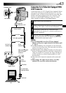
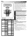
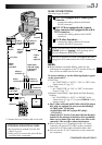
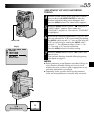
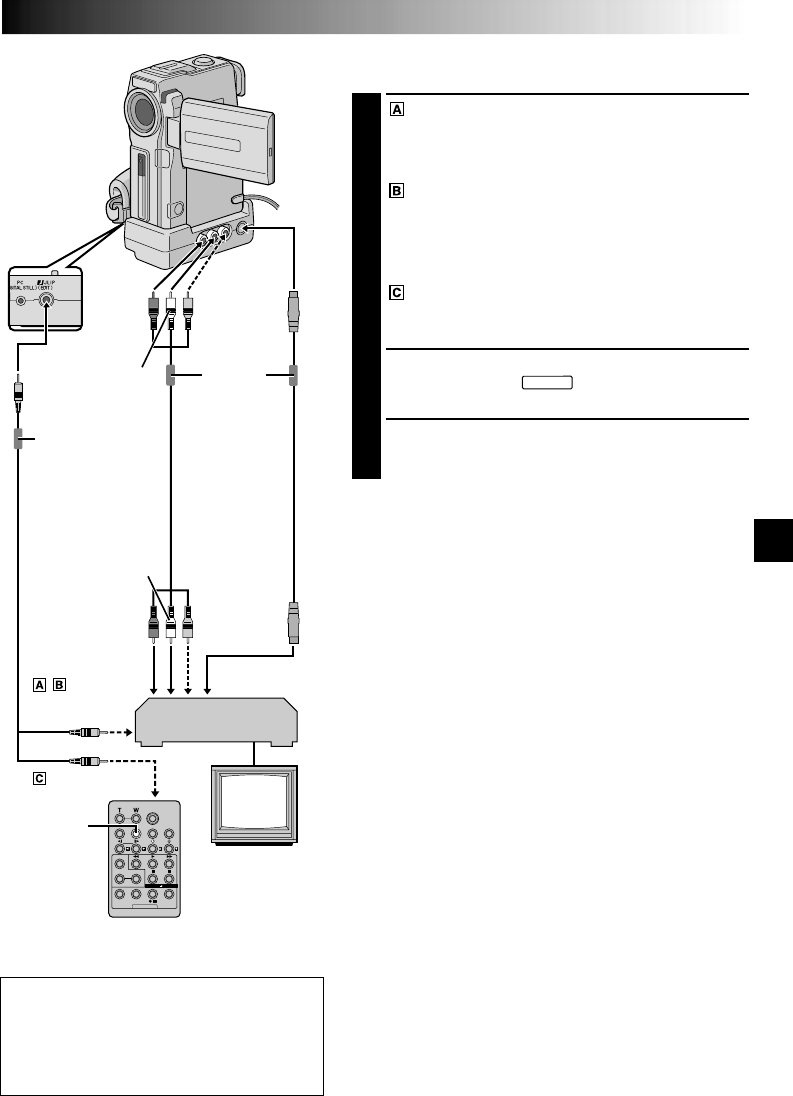
MAKE CONNECTIONS
Also refer to pg. 40 and 41.
1
A JVC VCR equipped with a remote pause
connector . . .
... connect the editing cable to the Remote
PAUSE connector.
A JVC VCR not equipped with a remote
pause connector but equipped with an R.A.
EDIT connector . . .
... connect the editing cable to the R.A.EDIT
connector.
A VCR other than above . . .
... connect the editing cable to the remote
control’s PAUSE IN connector.
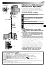
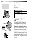
2
Insert a recorded tape into the camcorder and set the
POWER Switch to “
PLAY/PC
” while pressing down
the Lock Button located on the switch.
3
Turn the VCR power on, insert a recordable tape and
engage the AUX mode (refer to the VCR’s instructions).
NOTES:
●
Before Random Assemble Editing, make sure the
indications do not appear on the TV monitor. If they do,
they will be recorded onto the new tape.
To choose whether or not the following displays appear
on the connected TV . . .
•Date/Time
.... set “DATE/TIME” to “AUTO”, “ON” or “OFF” in the
Menu Screen (੬ pg. 37).
•Time Code
.... set “TIME CODE” to “ON” or “OFF” in the Menu
Screen (੬
pg. 37).
•Playback Sound Mode, Tape Speed And Tape Running
Displays
.... set “ON SCREEN” to “LCD” or “SIMPLE” in the
Menu Screen (੬ pg. 37). Or, press DISPLAY on the
remote control.
●
The S-Video cable and Audio/Video cable (RCA plug to
RCA plug) are optional. Be sure to use the following:
•
S-Video cable: YTU94146A
•
Audio/Video cable (RCA plug to RCA plug):
YTU94147A
Consult the JVC Service Center described on the sheet
included in the package for details on their availability.
Make sure to connect the ends with a core filter to the
camcorder. The core filter reduces interference.
●
When editing on a VCR equipped with a DV input
connector, an optional DV cable can be connected
instead of an S-Video cable and audio/video cable.
●
You can use the AV OUT connector on the camcorder
for connection.
CONTINUED ON NEXT PAGE
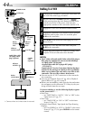
To
Remote PAUSE
or R.A.EDIT
VCR
TV
White to
AUDIO L IN
Red to
AUDIO R IN
To
S-VIDEO IN
To PAUSE IN
Editing
cable
(provided)
S-Video
cable
(optional)
Audio/Video
cable [RCA plug
to RCA plug]
(optional)
Yellow to
VIDEO IN*
* Connect when an S-Video cable is not used.
To JLIP
(EDIT)
To
S-VIDEO
Core filter
Core filter
ATTENTION FOR EDITING CABLE
• Be careful not to mistake it for the JLIP
cable (੬ pg. 6).
• Make sure you connect the end with the
core filter to the camcorder.
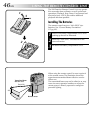
Red to
AUDIO
R OUT
Yellow to
VIDEO
OUT*
White to
AUDIO
L OUT