


C O N N E C T I O N S 5
1) Refer to the connection instructions in the user’s
guide for each component you plan to connect.
They will provide more detailed information about
their products, and they will tell you what plugs and
cables are required.
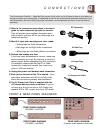
2) Most A/V input jacks and plugs are color coded:
• Yellow plugs are Video connections
• Red plugs are for Right Audio connections
• White plugs are Left Audio (Mono) connections
3) Perform one hookup at a time.
If you have many accessories to connect, make sure
each connection is correct by checking to see that it
works properly before attempting the next connection.
(For example, always start with the RF or Cable
connections, make sure it works, then move on to
video or VCR connections.)
4) Unplug the power cord between each connection.
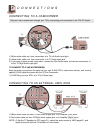
5) Each jack on the back of the TV is labeled. If you
read these instructions and still do not fully under-
stand the connections process, seek assistance.
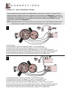
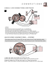
6) The AV Compu Link Cable is supplied with the
JVC device which you want to connect. If you do
not have one, but you do have a JVC Compu Link
capable VCR or HiFi, contact your local JVC dealer.
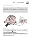
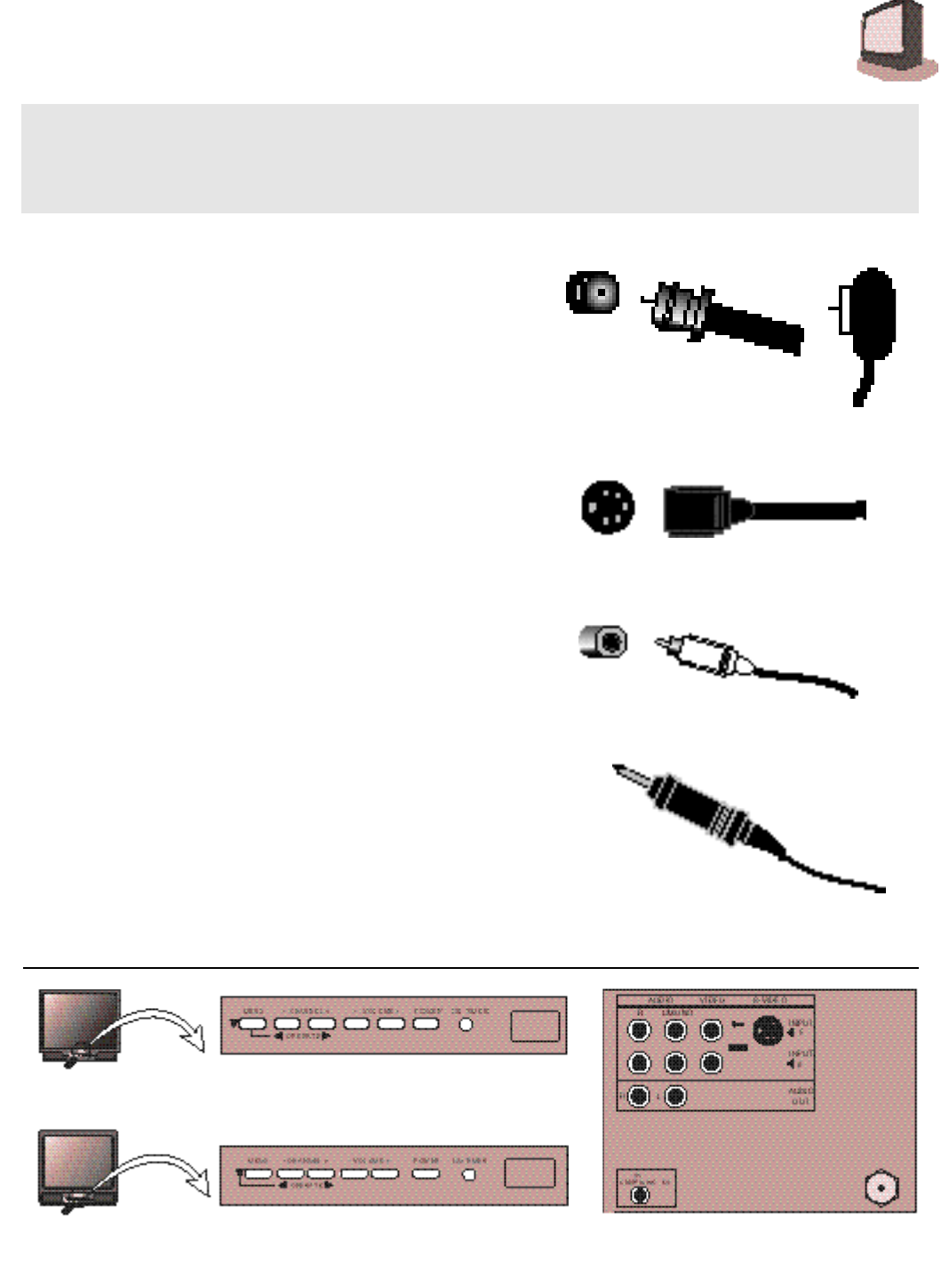
RF Connectors
AV Compu Link Cable
A/V Input Plug
S-Video Plug
The Connections Checklist — Read Me First! section of this guide is a list of ideas to keep in mind when you
set out to perform your connections. It is designed to help us not-so-technically-advanced individuals. If you
read this section, and can’t identify the plugs, connectors, and components you have, do not be afraid to
seek help.
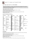
FRONT & REAR PANEL DIAGRAMS
FRONT PANEL DIAGRAM
AV-32950 • AV-27950
FRONT PANEL DIAGRAM
AV-36950 • AV-35955
REAR PANEL DIAGRAM
Common to all models in this book.