


8
Introduction
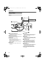
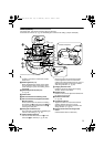
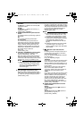
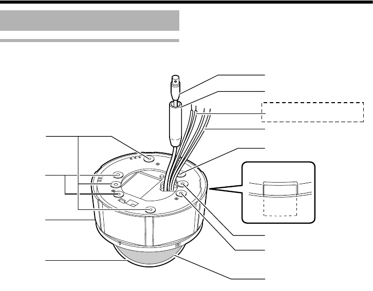
Camera
A
Mounting hole (elliptical) x 4
Use these when mounting the camera to the
electrical box. (A pg. 22)
B Mounting hole (round) x 4
Use these when mounting the camera to the
ceiling or wall. (A pg. 18, 20)
C Outer Case
Use this in the following cases:
●When mounting the camera directly to the
ceiling or on the wall. (A pg. 20)
●When mounting the camera to the electrical
box. (A pg. 22)
D Dome Cover
The dome cover is fragile. Take care when
handling it.
E Inner Dome
Before mounting the camera, remove it and
perform switch setting and image angle
setting. (A pg. 18, 20)
F Wiring Hole
Break and use this when drawing the cable
from the camera unit without drilling a hole in
the ceiling. (A pg. 22)
G Input Power cable
DC 12 V Input: Red (+12 V), Black (GND)
AC 24 V Input: Non-polar. (A pg. 16)
H Alarm signal cable (TK-C215V12 only)
Yellow (ALARM IN), Gray (ALARM GND).
(A pg. 15)
I Protection Cover
Upon connecting the coaxial cable, protect it
by insulating the metal part of the BNC
connector from the ceiling structure.
J Video signal output connector (BNC)
(A pg. 14)
Name of Parts
B
D
C
A
J
I
G
A
F
B
B
E
H
TK-C215V12 only
TK-C215V4_V12_EN.book Page 8 Wednesday, August 2, 2006 1:18 PM