


3
☞ Continued overleaf
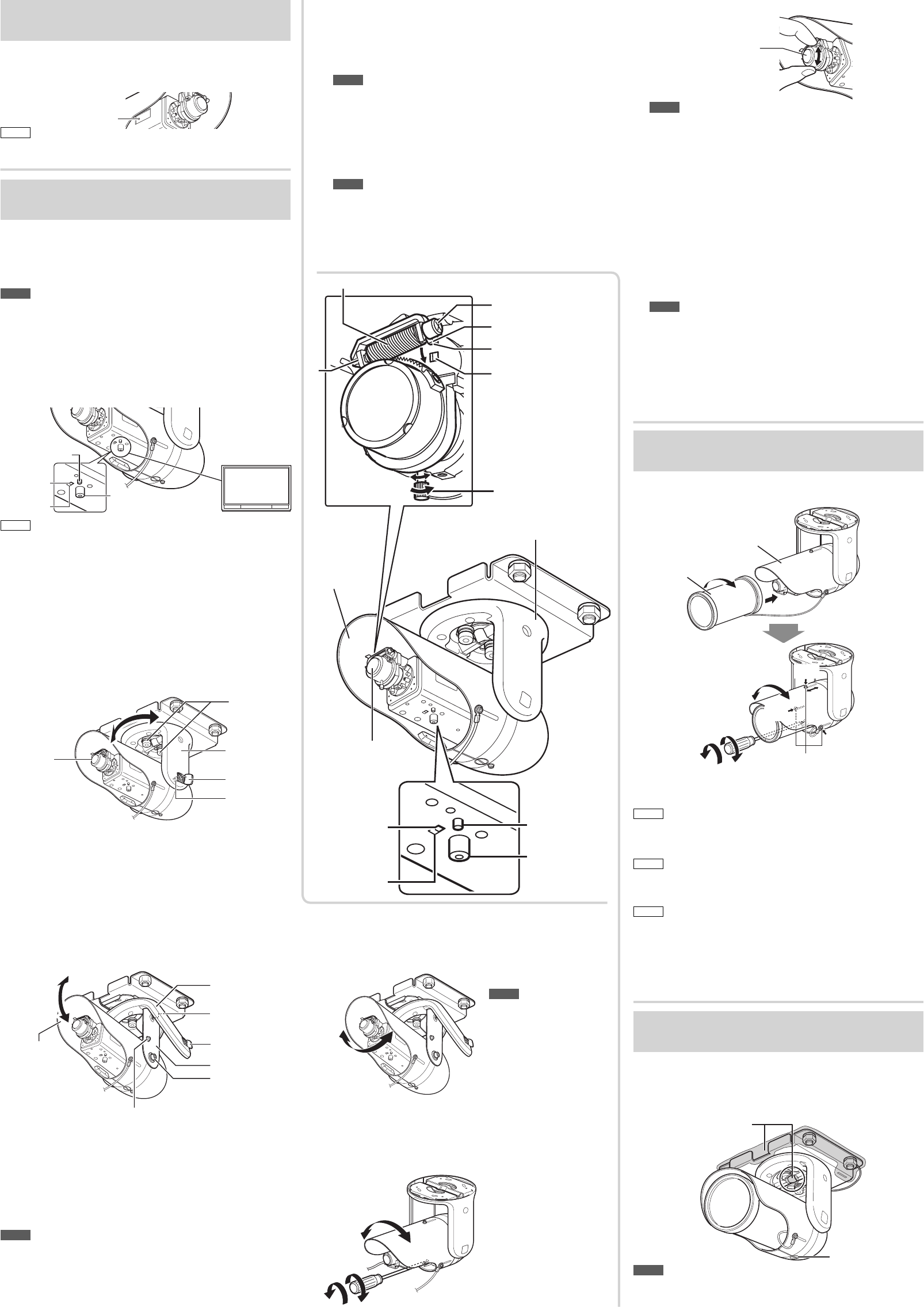
5 Adjust the rotation angle of the camera
(When the camera is mounted on the wall only)
Adjust the rotation angle of this camera to level the image of the
camera. The range of rotation adjustment is about 110 degrees.
4
Rotation angle
Note
•
Do not hold the lens
section when adjusting the
direction of the camera.
Applying force to the zoom
adjustment ring while
adjusting the image size
may result in damage.
6 Rotate the sunshade. (When the camera is
mounted on the wall only)
Rotate the sunshade after adjustment of the rotation angle. The
procedure is below.
6
2
1
Rotation the
direction of the
sunshade
1 Loosen the screw at the
bottom of the camera,
and rotate the sunshade.
2 Fasten the screw after
the adjustment.
Adjust the field angle and focus
1 Adjust the zoom ratio.
1 Loosen the fastening screw of the zoom adjustment ring, then
move the ring to the right and left to adjust the zoom ratio. After
completing the adjustment, tighten the setscrew.
Note
• Applying force on the zoom adjustment ring while adjusting the
image size may cause damage.
Moving the zoom adjustment ring beyond its adjustable range
may cause the performance of this camera to deteriorate.
2 Roughly adjust the focus.
1 Lift the focusing gear control, release the catch from position A
and insert it into position B to disengage the gear.
Note
• If you open the gear beyond position B, the gear shaft is
released from the bearing (C in the figure on the left) to prevent
it from being damaged. In this case, correctly re-insert the shaft
into bearing C and return it to the original position before using it.
2 Rotate the lens section at the tip to roughly adjust the focus.
Lens section
2
Note
• Do not hold the lens section when adjusting the direction of the
camera. The lens section may be damaged if you apply force to
it. Also, exercise care not to leave your finger prints on the lens
when you rotate the lens section.
3 Return the catch to its original position, and then return the
focusing adjustment gear to its original position.
3 Connect the camera to a computer, and open the
Built-in Viewer.
• For details about computer settings and methods for connecting
the camera to a computer, refer to “Instructions (IP Address
Settings)”.
4 Select “Day Focus Adjust” from the “Focus” page
in “Advanced Settings”.
• The focus position is automatically adjusted.
• For details on back focus, refer to “Instructions (Setting)” on the
supplied CD-ROM.
Note
• It may be difficult to acquire focus the following places.
– Too bright places.
– Too dark places.
–
Places where brightness always flickering; people are passing by
– Places where there is little contrast
– Places where there are repeating
• The focus position can be manually adjusted by using the Built-
in Viewer installed on your computer connected to the camera.
(☞ “Instructions (Setting)”) Resort to this method if it is difficult
to acquire focus automatically.
After all connections and installations are completed, turn on the
power of the unit. When the camera is booting, the [STATUS]
indicator lights up orange. It lights up green after booting.
[Status] indicator
Memo
•
The lighting status of the [STATUS] indicator can be checked via the
opening on the side of the camera.
Adjust images by watching them on the monitor.
* The diagram depicts the camera directly mounted on the ceiling for
explanation purposes.
The same procedures are performed when mounting the camera on
the wall with the cables pulled out.
Note
• Before you touch the camera, be sure to touch the metal surface of
the monitor terminal first in order to discharge static electricity.
Otherwise, static electricity may cause the camera to malfunction.
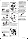
Adjust the shooting direction of the camera
1
Connect a test monitor to the [MONITOR] terminal.
2
After checking that the [MONITOR] selection switch
is set to “NTSC”, press the [FOCUS ASSIST] button.
2
1
Test monitor
75 Ω
termination
[MONITOR]
terminal
[Focus Assist]
Button
[MONITOR]
SELECT SW
NTSC
PAL
Memo
•
The camera has a 16:9 aspect ratio. If the test monitor has a 4:3 aspect
ratio, the camera image is converted into 4:3 ratio and displayed.
• Set to “NTSC” when connecting to an NTSC monitor, or set to “PAL”
when connecting to a PAL monitor, then hold down the [RESET]
button for approximately three seconds to reboot. While the camera
is rebooting, the [STATUS] indicator lights up orange.
•
If you keep pressing the [RESET] button for more than 5 s, the camera
enters the Service mode. Do not press this button for more than 5 s.
3 Adjust the shooting direction of the camera.
1 Loosen the 2 bolts (M8) which fix the camera to the mounting
bracket with the wrench (provided).
2
Adjust the pan-direction to face the lens toward the subject, holding
the stay cover. The range of adjustment angle is about ± 50°.
3 Fasten the two bolts to fix the camera direction.
3
4-1
Lens section
Stay cover
Cap
Pan-direction adjustment
Bolts
(M6, 2-places)
Bolts
(M8, 2-places)
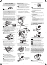
4 Adjust the tilt angle direction of the camera.
4-1 Roughly adjust the tilt angle direction of the camera
1 Open the cap (2-places) on the side of the stay cover.
2 Loosen the 2 bolts (M6) with the wrench (supplied).
3 Take the sunshade, and adjust the tilt angle.
You can adjust by about 18 degrees for each step.
4 If fine adjustment of the tilt angle is necessary, fasten the 2 bolts
(M6) temporarily, and go to step 4-2.
5 If fine adjustment of the tilt angle is unnecessary, fasten the 2
bolts (M6) with the specified amount of torque, and fix the cap.
4-2 Finely adjust the tilt angle direction of the camera
4
-2
2,4
4
-2
6
4
-2
1,5
4
Cover
Bolt (M6, 2-places)
Sunshade
Screw
Bolt (M4)
Stay cover
Cap
Tilt angle
direction
1 Loosen the screw on the right side of the Stay Cover, and open
the cover.
2 Loosen the bolt (M4) with torque wrench.
3 Take the sunshade, and adjust the tilt angle. The range of
adjustment is limited within 20 degrees (approx.).
4 Fasten the bolt (M4) with the specified amount of torque.
5
Set the cover on the stay cover opened in step 1, and fasten the screw.
6 Securely fasten the 2 bolts (M6) that you fastened temporarily
with the specified torque at 4 of step 4-1, and put on the cap.
Note
•
Fine adjustment of the tilt angle should be done when the bolt (M4)
is loose. If you adjust the tilt when the bolt is tightened, the bolt may
become loose.
• After adjusting the tilt angle and deciding the tilt position, make sure
to tighten the bolts (M6 and M4) on both sides of the stay cover to
the torque specified below.
-M6: Greater than 3.93 N•m; M4: Greater than 0.98 N•m
Adjust the sunshade.
1
Front cover
Sunshade
6
2
4
3,5
3,5
3,5
Screws for fixing sunshade (3-places)
1
Turn the front cover clockwise, and attach it to the camera.
Confirm that the front cover is securely attached.
2 Loosen the screw on the bottom of the camera.
Memo
• Use a long screw driver to avoid damaging the front cover.
3 Loosen the 3 sunshade fixing screws.
Turn the sunshade slightly if it is hard to loosen the screws.
Memo
• If you remove the sunshade fixing screws, the fall prevention wire
comes off. Do not remove the sunshade fixing screws.
4
Move the sunshade back and forth, and adjust the position.
Memo
• Adjust the sunshade when flares or ghosting appear.
• The sunshade may appear in the image of the camera due to the
angle of the lens and the position of the sunshade.
5
Fasten the sunshade fixing screws after adjustment.
6 Rotate the sunshade to a suitable position, and
fasten the screw on the bottom of the camera.
Sunshade
Stay cover
Lens
Focus adjustment gear
Knob
Zoom adjustment ring
Catches
A
B
C
[Focus Assist] Button
[MONITOR]
terminal
[MONITOR]
SELECT SW
NTSC
PAL
Turn on the power
Image Adjustment
Adjust the sunshade
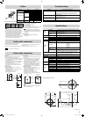
Perform dustproofing and waterproofing
For dustproofing, insert sealing material (GE silicon) into
the cable extracting space and gaps of the mounting
bracket, as well as the center hole of the stay cover.
Sealing material
Screw
Note
• Do not loosen the screw on the bottom of the camera. Loosening
or removing it may lead to water and moisture getting inside and
fogging the lens and the front cover.
Dustproofing, waterproofing
EN_VN-H157WVP_001B_Non-Mask.indb3 3EN_VN-H157WVP_001B_Non-Mask.indb3 3 5/25/2012 11:59:03 AM5/25/2012 11:59:03 AM