4
1. CS mount: connect the 1/3-type CS mount lens with the camera
2. Screw: lock Back focus Adjustment
3. Back focus Adjustment
4. Base: connect the camera with the tripod
5. SD card slot: insert a SD card into this slot for recording and storage
6. Video: not supported (for factory use only)
7. RJ45 Ethernet Connector/ PoE: insert the RJ45 cable for network connection. It also supports
PoE (Power over Ethernet).
8. Default Button: reset all of the camera parameters to factory default by pushing 5 seconds.
9. Reset Button: restart the system.
10. Power Indicator: Red light indicates power connection.
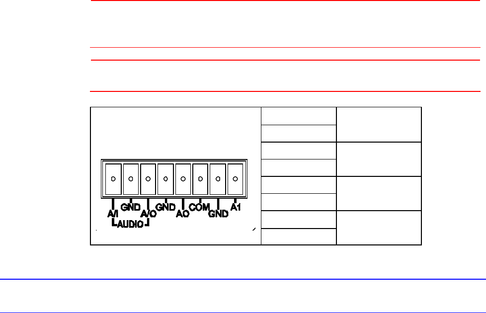
11. I/O Connector: Input/Output Connector
12. Power Terminal
Note
Connectors and field wiring terminals for external Class 2 circuits provided with
marking indicating minimum Class of wiring to be used. Class 2 shall be marked
adjacent to the field wiring terminals.
Caution
To avoid damage to the camera, never connect more than one type of power supply
(PoE or DC12V or AC24V power plug) at the same time.
A/I
GND
Audio in
A/O
GND
Audio out
AO
COM
Alarm out
AI
GND
Alarm in
Network Setup
Setting IP
This is a network-based camera and must be assigned an IP address first.
The camera’s default IP address is 192.168.0.2 and sub mask is 255.255.255.0. To change IP
address, open Network Settings page described later.
If your network uses a DHCP server, an IP address can be assigned automatically from the DHCP
server by enabling DHCP in the Network Settings page described later.
Connecting the Camera to a Personal Computer
1. Connect the network cable to the camera and then turn on the camera’s power.
2. Set the personal computer’s IP address. The camera’s default IP address is 192.168.0.2 and sub
mask is 255.255.255.0.
3. Check that the camera and computer are connected by Pinging the IP address you have set. To
do this, start a command prompt (Windows: from the Start Menu, select Program. Then select


