


12
Installation and Connection (WB-1550U)
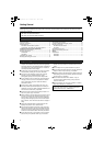
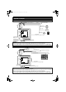
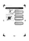
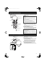
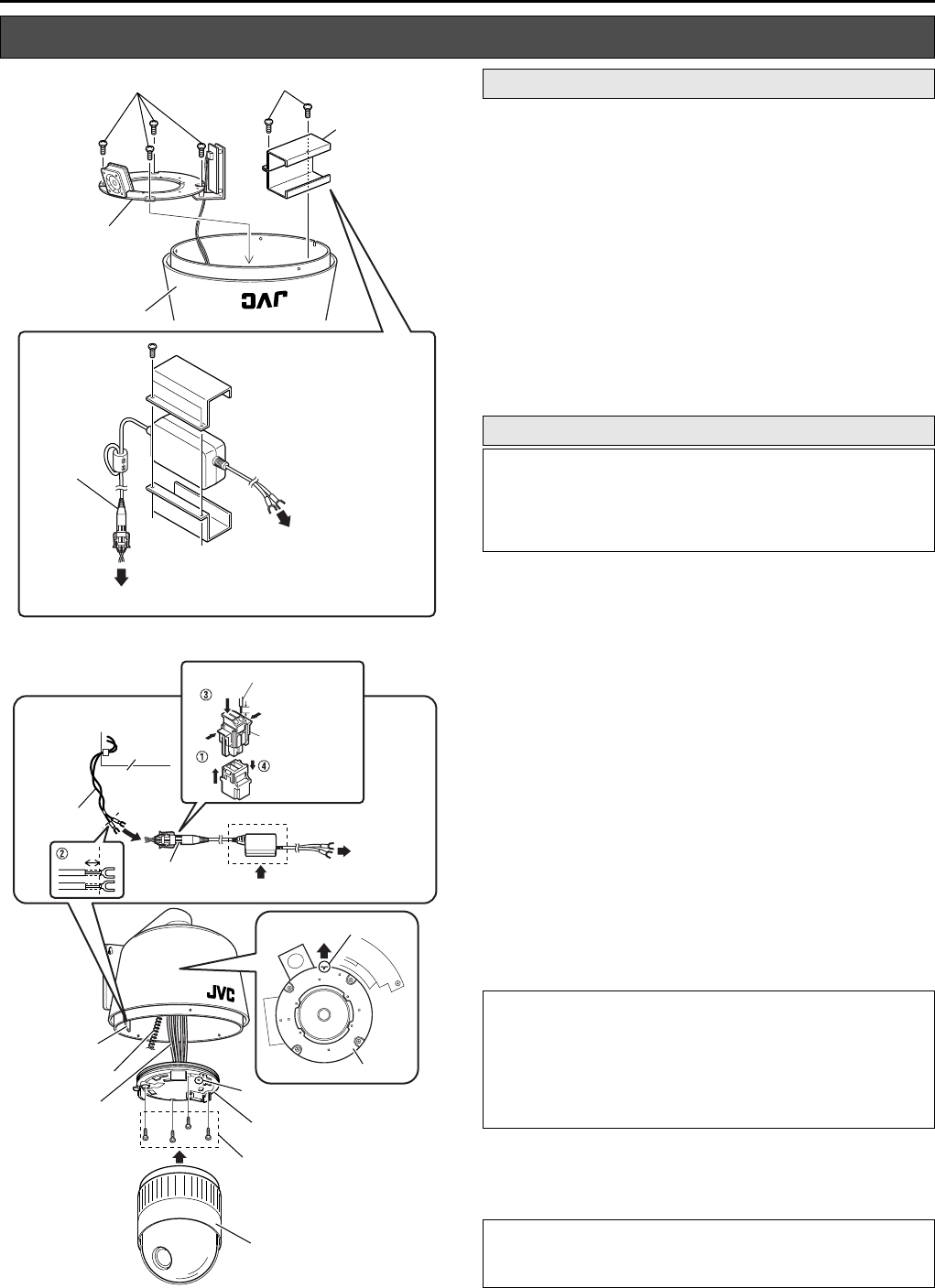
1. Dismantle the camera mounting bracket
Loosen the screws on the camera mounting bracket (M4,
4 pcs) using a driver to dismantle it.
2. Dismantle the converter unit mounting bracket
Loosen the screws on the converter unit mounting bracket
(M3, 2 pcs) using a driver to dismantle it.
3. Mount the converter unit to the housing
Clamp the converter unit using the converter unit
mounting bracket, followed by mounting it to the housing
using the screws (M3, 2 pcs) removed in Step 2.. When
mounting, pay attention to the orientation of the converter
unit as shown in the left diagram.
4. Mount the camera mounting bracket
Mount the camera mounting bracket dismantled in step 1.
to the housing. Mount it exactly to the original position.
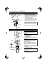
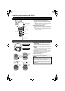
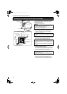
1.
Connect the AC 24 V output cable to the converter unit.
Follow the procedures below to connect the AC 24 V
output cable of the main board on the main housing unit to
the converter unit.
A Push both ends of the connector as shown in the left
diagram to remove it from the supplied converter unit.
B Cut the Y terminal of the AC 24 V output cable and peel
off about 5 mm of the coating.
C Push the arrow mark using tools such as a flat-head
screwdriver to insert the coating of the AC 24 V output
cable into the connector.
D Attach the connector to the converter unit.
2.
Mount the Y terminal of the converter unit to the
ceiling mount of VN-C655U.
Guide the Y terminal of the converter unit through the
ceiling mount cover, followed by connecting it to the
[POWER INPUT DC 18 V] terminal of VN-C655U’s ceiling
mount.
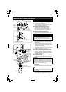
3. Connect other cables
Connect the necessary cables supplied with the housing
(coaxial video cable, alarm signal cable, LAN cable, etc.)
to the corresponding terminals on the ceiling mount.
4. Mount the camera’s ceiling mount to the main
housing unit.
Use the screws supplied (4 pcs) to mount the ceiling
mount to the main housing unit.
5. Mount the camera to the ceiling mount
Follow instructions in the manual of the camera in use to
mount the camera to the ceiling mount.
Mounting the Camera (VN-C655U)
1. 2.
4.
3.
Connector
Connect to AC 24 V Output Cable
To [POWER INPUT DC 18 V]
Terminal of Ceiling Mount
Screw (M4) x 4
Camera Mounting
Bracket
Main Housing Unit
Screw (M3) x 2
Converter Unit
Mounting Bracket
5mm
Press
Press
Press
5mm
1.
2.
4.
5.
3.
Main Board
AC 24 V Output Cable
Connector
Interior of Housing
To [POWER
INPUT DC
18 V]
Terminal of
Ceiling
Mount
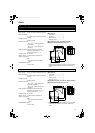
Safety Wire
Camera
Notch
Camera Mounting Bracket
Cables
AC 24 V
Output Cable
Main Board
Screws Supplied (4 pcs)
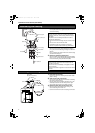
JVC Mark
F Mark
Ceiling Mount
Connector
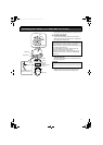
Preparation
Mounting
Before mounting.
Remove the ceiling mount cover of the camera and guide the
cables supplied with WB-1550U through the cover.
T For further details, please refer to the instruction manual of
the camera in use.
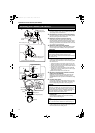
CAUTION:
●
Connect the communication cable to the alarm terminal if
necessary.
In addition, DC 12 V Power Cable is not in use
on this system.
For safety reasons, ensure to cut off any
excess cable and bind using an insulating tape before use.
● For further details on connection, please refer to the
instruction manual of the camera in use.
NOTE:
During mounting, align the
F
mark of the ceiling mount with the
notch on the camera mount bracket of the main housing unit.
VN-C655
WB-1540_1550.book Page 12 Thursday, May 17, 2007 3:21 PM