


10
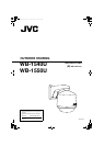
Installation and Connection (WB-1550U)
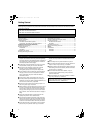
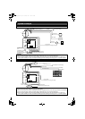
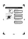
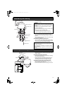
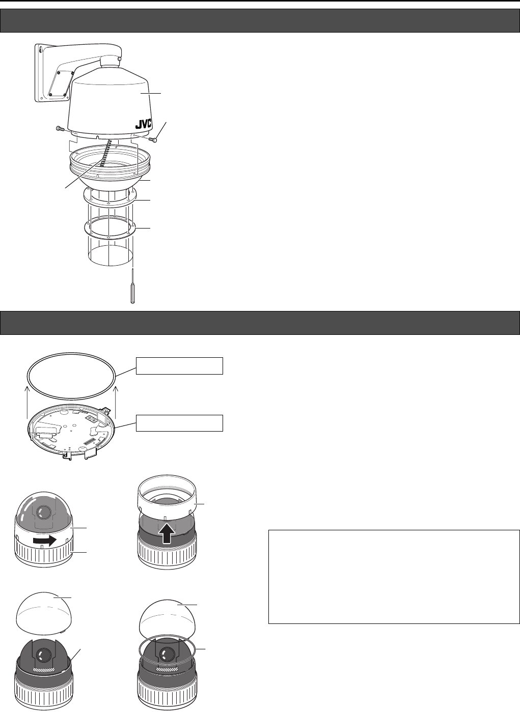
1. Dismantle the gasket and gasket gland
Loosen the 8 Screws B (M4) using a driver, followed by
dismantling the gasket and gasket gland from the lower
housing.
T The 8 Screws B (M4) cannot be totally removed from
the gasket to prevent it from falling off.
2. Dismantle the lower housing
Loosen the 3 Screws A (M4 x 6) using a driver, followed
by dismantling the lower housing from the main housing
unit.
T The lower housing is connected to the main housing
unit using a safety wire.
1.
2.
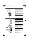
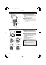
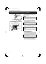
1. Dismantle the rubber gasket of the camera’s
ceiling mount
Dismantle the rubber gasket (white) on the same side as
the ceiling mount of the combination camera to be
installed.
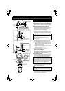
2. Dismantle the rubber gasket in the interior of the
camera
Follow the procedures below to remove the rubber gasket
from the interior of the combination camera.
A Turn the camera body cover in the direction as indicated in
the left diagram.
(When the camera body cover is tight and cannot be
turned, do so upon fastening the main unit.)
B Dismantle the camera body cover.
C Dismantle the dome cover.
D Remove the rubber gasket and restore the dome cover and
camera body cover to their original positions.
Disassembling the Housing
2.
1.
Safety Wire
Main Housing Unit
Screw A (M4 x 6) x 3
Lower Housing
Gasket
Gasket Gland
Screw B (M4) x 8
Procedures Before Mounting the Camera
Rubber Gasket (White)
Ceiling Mount
C
A
D
B
Camera
Body Cover
Main Unit
Dome Cover
Camera
Body
Cover
Dome
Cover
Rubber
Gasket
Rubber
Gasket
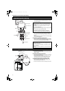
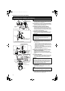
CAUTION:
● The combination camera is an enclosed unit. In order to
prevent fogging in the interior of the dome cover, ensure to
remove the rubber gasket (2 types) before use.
● Do not remove the combination camera from the housing
and use it singly after removing the rubber gasket and
installing to the housing. Doing so may cause the camera
to malfunction.
WB-1540_1550.book Page 10 Thursday, May 17, 2007 3:21 PM