11
1. Connect the AC 24 V output cable to the camera
Connect the AC 24 V output cable to the ceiling mount of
the camera to be installed.
2. Connect other cables
Connect the coaxial video cable and communication
cables (alarm signal, control terminal, etc.) supplied with
the housing to the ceiling mount.
3. Mount the ceiling mount of the camera to the
main housing unit
Use the 4 screws supplied to mount the ceiling mount to
the main housing unit.
4. Mount the camera to the ceiling mount
Follow instructions in the manual of the camera to be
installed to mount the camera to the ceiling mount.
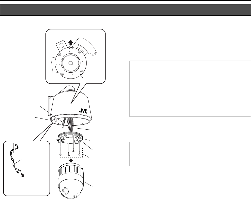
Mounting the Camera (TK-C655E and TK-C676E)
1.
2.
3.
4.
Interior of Housing
Notch
Camera Mounting Bracket
Safety Wire
Main Board
AC 24 V Output
Cable
To [POWER INPUT AC 24 V]
Terminal of Ceiling Mount
Cables
F Mark
Ceiling
Mount
Screws Supplied
(4 pcs)
Camera
JVC Mark
CAUTION:
● Connect the communication cable to the [ALARM IN/OUT]
and [CONTROL] terminals if necessary. For safety
reasons, ensure to cut off any excess cable and bind using
an insulating tape before use.
● For further details on connection, please refer to the
instruction manual of the camera in use.
● Ensure to bind connectors of LAN cables and DC 12 V
Power Cable that are not in use with an insulating tape
before use.
CAUTION:
During mounting, align the F mark of the ceiling mount with
the notch on the camera mount bracket of the main housing
unit.
TK-C655 and TK-C676
WB-1540_1550.book Page 11 Thursday, May 17, 2007 3:21 PM


