


8
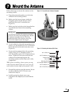
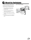
Follow these steps to connect the data, power,
and RF cables to the antenna.
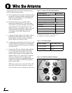
a. First determine the number of RF coax cables
required for your particular installation (see
Figure 12). (See Figure 13 to determine the
type of cable required.)
b. Route the data, power, and RF cables
belowdecks through the 3" (80 mm) cable
access hole. Leave an adequate service loop,
approximately 8" (20 cm) of slack, in the
cables for easy serviceability. Later, you will
connect the data and power cables to the
switchplate and the RF cable(s) to the
receiver(s).
c. Connect the data cable to the “Data” jack on
the bottom of the antenna (see Figure 14).
Hand-tighten until the connector locks in
place; do not use excessive force.
d. Connect the power cable to the “Power” jack
on the bottom of the antenna. Hand-tighten
until the connector locks in place; do not use
excessive force.
e. Connect the RF coax cable(s) to the antenna.
If you need to connect just one RF cable,
connect the cable to the “RF1” jack on the
bottom of the antenna. Hand-tighten, then
tighten with a 7/16" wrench for 1/4 turn to
ensure an electrical and weather-proof
connection. Connect any additional RF coax
cables to the antenna’s RF2, RF3, and RF4
jacks, in that order.
TIP: If you connect two or more RF cables, label
both ends of each cable to match the connector.
This will make it easier to identify the cables later.
Figure 12: Number of RF Coax Cables Required
* Multiswitch required for 3 or more receivers.
** Multiswitch required for 5 or more receivers.
See Appendix A on page 21 for details.
Connecting to: # RF Cables
System with Dual LNB
1 receiver 1
2 or more receivers 2*
System with Quad LNB (Europe Only)
1 receiver 1
2 receivers 2
3 receivers 3
4 or more receivers 4**
Figure 13: RF Cable Guidelines
Cable Length Use Cable Type
<= 75 ft (23 m) RG-6
> 75 ft (23 m) RG-11
Figure 14: Connectors on Bottom of Antenna
DataPower
Wire the Antenna
6