


2524
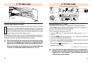
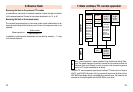
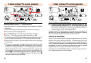
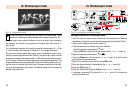
Fig. 15: Settings for TTL remote operation
Setting procedure for Metz TTL remote operation:
• Adjust the camera to TTL mode, as explained in the manufacturer’s Operating
Instructions.
1 Switch on the flashgun mounted on the camera with the main switch
ቢ
.
2 Set the operating mode selector
ቯ
to TTL.
3 Press the Remote button
ብ
on the flashgun mounted on the camera.
4 Use the „+“ button
ቪ
to select the controller address Co 1 or Co 2.
•
Fit each slave with an SCA 3080 Slave Adapter, switch on with the main switch
ቢ
,
and set the operating mode selector to TTL:The slaves are now in slave mode.
5 Press the manual firing button
ተ
on the flashgun mounted on the camera and
fire a test flash.
•
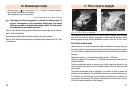
The slave unit responds with a delayed flash, thus confirming that it is ready
for operation. If several slaves are used at the same time, all will react simul-
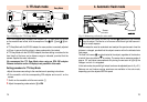
taneously.The LC display indicates SL 1 or SL 2, depending on the controller
address selected (Fig. 15). If, after a test flash has been fired, proper function
is not confirmed by one of the slave units in the form of a delayed flash, then
the sensor
²
in the SCA adapter has not received any light pulse. Should this
be the case, rotate the rotary base
»
of the flash unit so that the sensor
²
can receive a light pulse, and repeat step 5.
7. Metz cordless TTL remote operation
1
2
5
3
4
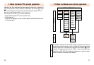
7. Metz cordless TTL remote operation
Fig. 16: Display for operation with slaves
A particularly short distance between controller and slave unit may
cause the camera’s electronics to cut off the flash before the slave
has received its light pulse. In such an event widen the distance or
choose a larger f-number and repeat step No. 5.
To ensure that two TTL remote systems in the same room do not interfere with
each other, two different addresses can be selected on the controller. These are
then automatically transferred to the slave units after a test flash.
Checking the slave address:
The Co1 or Co2 controller address is permanently adjusted after a test flash has
been fired in the manner described in step No.5.The address setting can only be
changed by switching the slave off and on again, and by repeating the steps No.
4 and 5. Please check the display to establish the address to which the slave has
been adjusted. Co1 and SL1 indicate that the controller and slave unit are both
adjusted to address 1.Alternately, Co2 and SL2 indicate address 2.
rA1 and rA2 (not with SCA 3080-M1 adapter) in the distance range indication on
the LC display can be ignored in these instances.
☞