


USER GUIDE
NI Smart Camera I/O Accessory
This document describes the features of the NI Smart Camera I/O Accessory, what you need to get
started, installation and operation instructions, and accessory specifications.
The NI Smart Camera I/O Accessory features the following:
• Spring terminals for two isolated inputs
• Spring terminals for two isolated outputs
• Spring terminals for the quadrature encoder inputs
• Two power connection options
• An RS-232 connector to communicate with the smart camera serial port
• User-replaceable fuses for isolated outputs, RS-232, and accessory power
• Built-in DIN rail clips for easy mounting
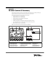
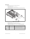
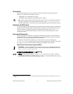
Figure 1 shows the accessory circuit board parts locator diagram.
Figure 1. Front and Back Views of the NI Smart Camera I/O Accessory Circuit Board
1 Camera D-SUB Connector
2 RS-232 D-SUB Connector
3 24 VDC D-SUB Connector
4 Power In Selection Switch
5 24VDC Two-Position Connector
6 Isolated Output 1 Terminals
7 Isolated Output 0 Terminals
8 Quadrature Encoder Phase B Terminals
9 Quadrature Encoder Phase A Terminals
10 Isolated Input 1 Terminals
11 Isolated Input 0 Terminals
12 Spare Power Fuse
13 Power Fuse
14 Spare RS-232 Fuse
15 RS-232 Fuse
16 Isolated Output 0 Fuse
17 Spare Isolated Output Fuses
18 Isolated Output 1 Fuse
321
5
4
18
11 10 9 8 7 6
12 13
16
15
14
NATIONAL
INSTRUMENTS
NI SMART CAMERA
I/O ACCESSORY
17