NI Smart Camera I/O Accessory User Guide 6 ni.com
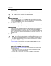
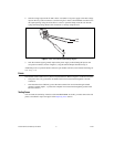
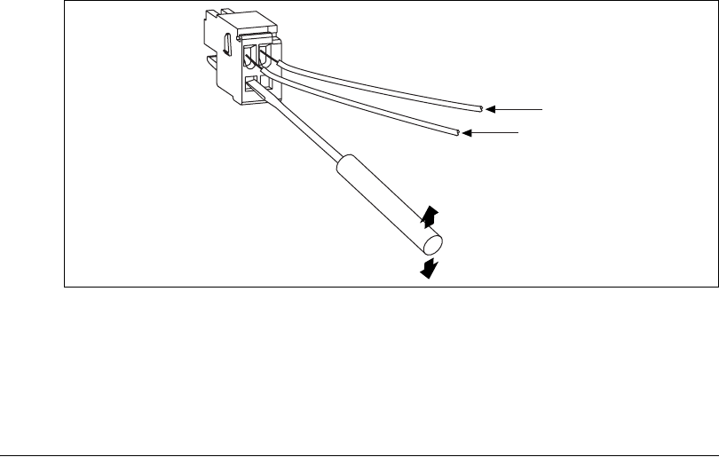
2. Wire the voltage output of the 24 VDC +20%/–15% (IEC 1311) power supply to the main voltage
input on the two-position connector as shown in Figure 3. Insert a small flathead screwdriver into
the square opening. Using the screwdriver as a lever to open the clamp, insert the wire into the
spring terminal opening. Remove the screwdriver to securely clamp the wire.
Figure 3. Power Two-Position Header Wiring Diagram
3. Wire the common signal (ground) output of the power supply to the COM signal input on the
two-position connector, shown in Figure 3, using the same technique described in step 2.
Additional power two-position header connectors (part number 734-102) can be ordered from Wago at
www.wago.com.
Fuses
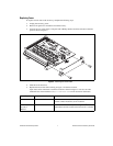
The NI Smart Camera I/O Accessory has four replaceable fuses. Refer to Figure 1 for the fuse locations.
• The power fuse (2 A), protects the NI Smart Camera from overcurrent through the +24 VDC
connectors.
• The other three fuses (200 mA), protect the smart camera from overcurrent through isolated
output 0, isolated output 1, or protect the computer from overcurrent through the ground on the
RS-232 connector.
Testing Fuses
You can check the continuity of the fuse with a handheld DMM. To do this, you must remove the side
panel, as described in steps 1 through 4 of the Replacing Fuses section.
+24 VDC
COM


