


Chapter 2 Parts and their functions
2
11
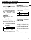
2 Either STEREO or MIX can be selected as the setting for the MONITOR
SELECT item by opening the <MIC/AUDIO2> screen from the VTR
MENU page by performing a menu operation.
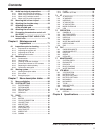
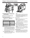
2-2 Audio function section (output system)
CH1/3 Audio channel 1 Audio channel 3
MONITOR SELECT CH1/2OCH3/4 selector switch
CH1/2 CH3/4
ST
Stereo
2
signals of audio
channels 1 and 2
Stereo
2
signals of audio
channels 3 and 4
CH2/4 Audio channel 2 Audio channel 4
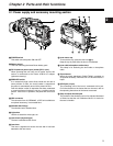
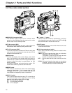
9 AUDIO OUT connector (XLR, 5-pin)
The audio signals recorded on audio channels 1 and 2 or
audio channels 3 and 4 are output from this connector.
With the AJ-SDC905 , the signals to be output
can be selected using the MONITOR SELECT
CH1/2OCH3/4 selector switch.
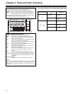
: MONITOR SELECT (audio channel)
CH1/2OCH3/4 selector switch
This is used to select the audio channels whose signals are
to be output to the speaker, earphone and AUDIO OUT
connector.
CH1/2 : The signals of audio channels 1 and 2 are output.
CH3/4 : The signals of audio channels 3 and 4 are output.
In addition, the channel indications for the audio level
meters appearing in the display window and viewfinder
change when this switch is operated.
MONITOR SELECT (stereo/mix)
STOMIX selector switch
This is used to select the sound which is to be output to the
speaker, earphone and AUDIO OUT connector.
ST: The stereo audio signals of channels 1 and 2 are
output.
MIX: The mixed audio signals of channels 1 and 2 are
output.
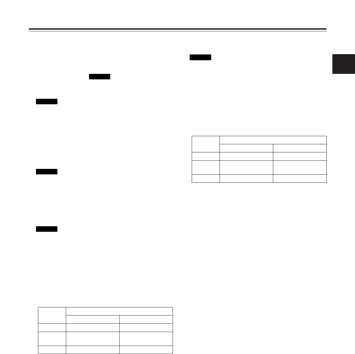
; MONITOR SELECT (audio selection)
CH1/3OSTOCH2/4 selector switch
This is linked with the MONITOR SELECT CH1/2OCH3/4
selector switch and used to select the sound which is to be
output from the speaker, earphone and AUDIO OUT
connector.
CH1/3 : The signals of audio channel 1 or 3 are output.
ST : The stereo audio signals of either audio channels
1 and 2 or audio channels 3 and 4 are output.
Using a menu setting, the stereo signals can be
changed to MIX signals.
CH2/4 : The signals of audio channel 2 or 4 are output.
SDC905
SDC615
SDC905
SDC905
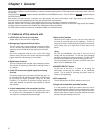
CH1 Audio channel 1 Audio channel 1
MONITOR SELECT STOMIX selector switch
ST MIX
1/2
Stereo signals of audio
channels 1 and 2
Mixed signals of audio
channels 1 and 2
CH2 Audio channel 2 Audio channel 2
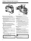
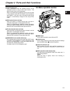
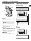
< MONITOR (volume) control
This is used to adjust the volume of the monitor speaker or
earphone.
= ALARM (warning alarm volume adjustment)
This is used to adjust the volume of the warning alarms
from the earphones which have been connected to the
speaker > or PHONES jack ?.
The warning alarms are not audible when this control is at
its lowest setting.
> Speaker
The EE sound during recording or the playback sound
during playback can be monitored through this speaker.
The warning alarms are output in synchronization with the
flashing or lighting of the warning lamps and warning
displays.
The sound heard from the speaker is automatically cut off
when earphones are connected to the PHONES jack ?.
? PHONES (earphones) jack (mini jack)
This is the earphone (stereo) jack which is used to monitor
the audio signals. When earphones are connected, the
sound from the speaker is automatically cut off. The sound
which is output from the two jacks (front and rear) is the
same.
@ DC OUT (DC power supply) output socket
This normally serves as the DC 12 V output socket. A
current of approximately 1 A can be supplied.
MONITOR SELECT (audio selection)
CH1O1/2OCH2 selector switch
This is linked with the MONITOR SELECT STOMIX
selector switch and used to select the sound which is to be
output from the speaker, earphone and AUDIO OUT
connector.
CH1: The signals of audio channel 1 are output.
1/2: The stereo audio signals of audio channels 1 and 2
are output. The stereo signals can be changed into
mixed signals using the MONITOR SELECT
STOMIX selector switch.
CH2: The signals of audio channel 2 are output.
SDC615