


3
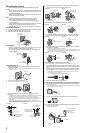
The camera’s external I/O interface allows you to connect a device, such as a sensor or motion detector, that can be used to trigger the camera’s image
buffering and transferring features (see Section 2 Using Triggers to Buffer and Transfer Images in the Operating Instructions on the CD-ROM), as well as
the detection notification sound feature (see Section 1.2.7 Detection Notification Sound in the Operating Instructions on the CD-ROM).
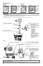
For BL-C121: Notes About Wireless Communication
The radio wave range may decrease depending on the surrounding environment or existence of obstacles. If obstacles such as the following are placed
between a camera and a router, radio waves will weaken. Therefore, even if the distance between the camera and router is short, the frame rate may
decrease or images may not be displayed.
• A metallic door or shutter
• A wall with an insulation material that contains aluminum foil
• A wall made of tin
• A wall made of concrete, stone or brick
• Fireproof glass
• Several walls separated by open space
• A steel shelf
In the example below, wireless communication between the camera and the wireless router is impaired due to steel doors or reinforced concrete walls
between the camera and the wireless router.
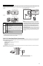
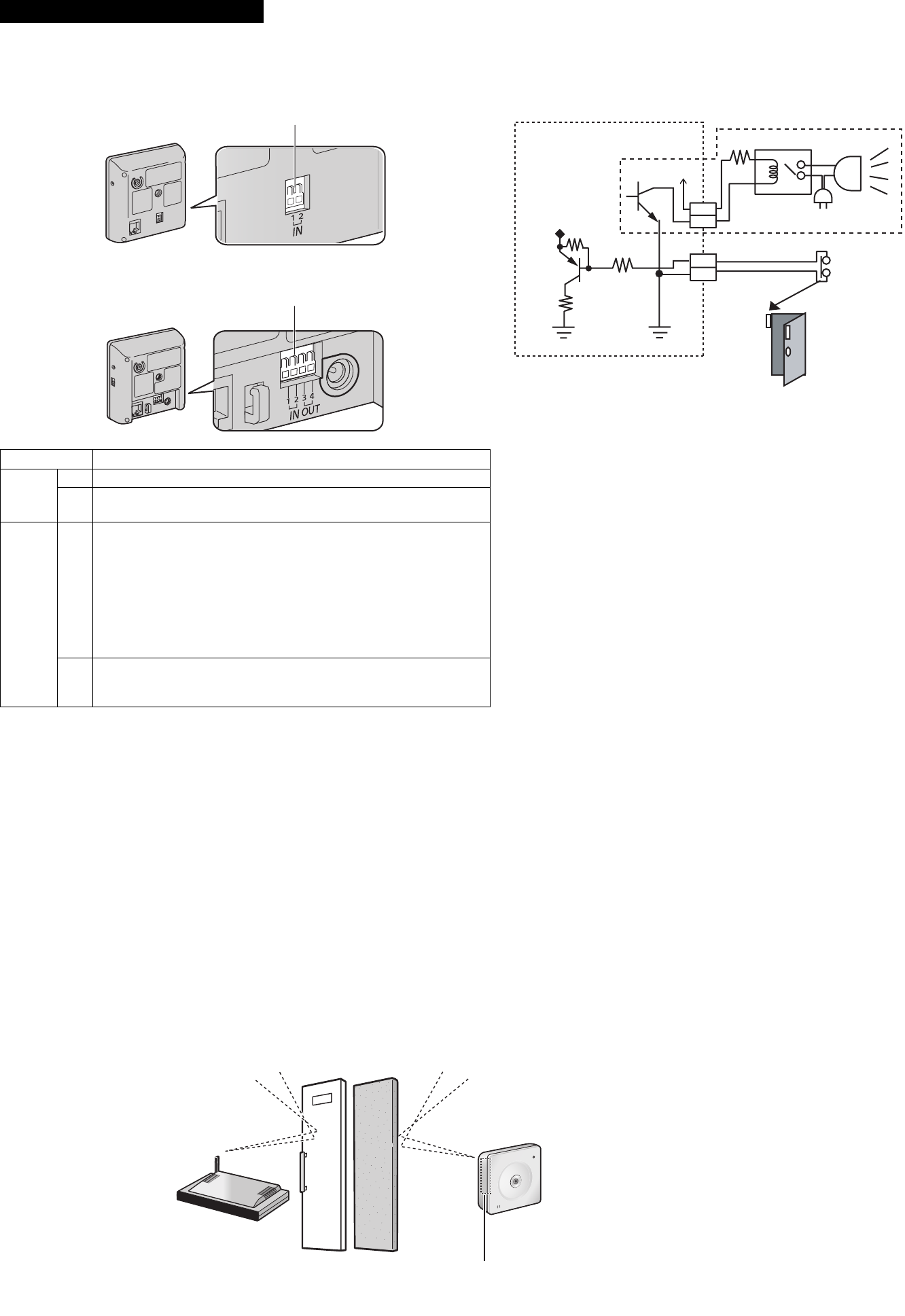
Connecting External I/O interface
BL-C101 Circuit Diagram Example
Caution
• The external I/O interface is not capable of connecting directly to
devices that require large amounts of current. In some cases, a
custom interface circuit (customer-provided) may have to be used.
Serious damage to the camera may result if a device that exceeds
its electrical capability is connected to the external I/O interface.
• Low voltage/current circuits and high voltage/current circuits are
used in the camera circuit. All wiring should be performed by a
qualified electrician. Incorrect wiring could damage the camera and
cause a fatal electric shock.
• External devices connected to the camera’s output terminals cannot
be controlled in the event of a network error or failure. Keep this in
mind when connecting door locks, heat-emitting devices, or other
devices that may be dangerous if they cannot be controlled. (BL-
C121 only)
BL-C121
Terminal Description
IN
1 GND terminal.
2
External sensor input. The camera can be triggered by either an open
circuit or a GND short-circuit.
OUT
BL-C121
only
3
External device control output. Allows you to control an external device
using the output buttons in the camera’s operation bar (for example,
turning a light on or off).
• This terminal’s behavior can be changed (see 7.4 Controlling the
External Output Terminal (BL-C121 Only) in the Operating Instructions
on the CD-ROM).
• This terminal is an open collector circuit. The maximum drawing
current is the same as terminal 4. Do not exceed the voltage of
terminal 4.
4
DC power output terminal.
• DC 8 V–10 V
• Maximum load is 100 mA.
Note
• If excessive force is used when disconnecting wires with pointed objects from
the external I/O interface, terminals may become damaged or the interface may
be pushed inside the camera body and become unusable.
External INPUT interface
Light
Door Sensor (Alarm)
Relay
Camera
9 V*
2
3
4
1
*DC 8 V–10 V
BL-C121 only
External I/O interface
Position the camera away from obstacles such as
steel doors or reinforced concrete walls.
Wireless antenna is built in the camera.