


16
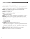
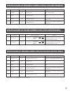
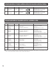
SPECIFICATIONS OF RS-485 CONNECTORS (FOR ACCESS CONTROL PANEL)
Differential input: ± 0.2 V or more
Differential output: ± 2 V or more
(When termination is ON)
Port NamePin No.
11
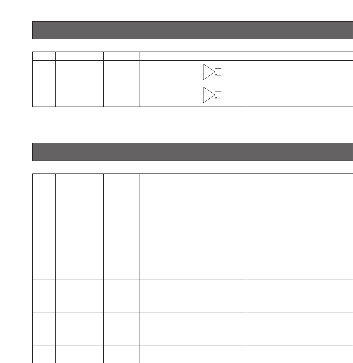
RS-485 (A)
IN/OUT RS-485 (A)
12
RS-485 (B)
IN/OUT RS-485 (B)
Differential input: ± 0.2 V or more
Differential output: ± 2 V or more
(When termination is ON)
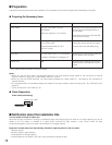
I/O Signal Description Remarks
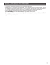
SPECIFICATIONS OF ALARM OUTPUT CONNECTORS
Remarks
0 V for ALARM OUTPUT
18
19
20
Pin No.
16
17
Port Name
OUTPUT
ACCEPT
OUTPUT
REJECT
OUTPUT
POWER
DETECTION
OUTPUT
TAMPER
DETECTION
GND
OUT
OUT
OUT
OUT
–
Recognition result output 1
(recognition ACCEPT)
Recognition result output 2
(recognition REJECT)
Alarm output 1
(power status)
Alarm output 2
(tamper detection)
Alarm output
(COMMON)
24 V, 24 mA
Open collector output
Normally Open contact
Active low, Pulse width: 0.1 s to 60 s
15
OUTPUT
RECOGNITION
START/
BUZZER
IN
Alarm input 1
(recognition start/buzzer)
0 V to 5 V, 24 mA (Max),
Active low,
Pulse width: 200 ms or more
24 V, 24 mA
Open collector output
Normally Open contact
Active low, Pulse width: 0.1 s to 60 s
24 V, 24 mA
Open collector output
Normally Close contact
24 V, 24 mA
Open collector output
Normally Open contact
Active low
I/O Signal Description
Note: You will set up Wiegand/RS-485 communication, pulse width of Recognition result output 1/2, and function of Alarm
input 1 with the administration software. Refer to system administrators.
(A)
(B)
(A)
(B)