


8
VQT5K48 (ENG)
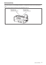
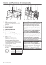
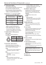
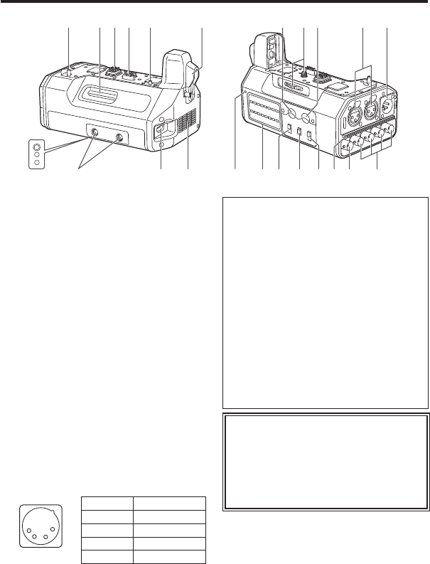
Names and Functions of Components
4 18 2 3 4 5 14141
11
8
109
1812131216 157 19617
1 HDMI connection terminal
Connects to the digital camera’s HDMI
connector.
2 Electrical contacts
3 Interface contacts
4 Camera attachment pins
5 Attachment screw
6 Screw hole (1/4-20 UNC)
Attaches to PL lens compatibility adapters,
etc.
7 HDMI terminal
HDMI Type A output terminal.
(VIERA Link is not supported.)
Use a high-speed double-shielded
4K-compatible HDMI cable (up to 2 m)
that is marked with the HDMI logo when
connecting to this terminal.
8 DC IN terminal
Connects to the DC power supply (battery:
12 V DC).
1
2
3
4
Pin no. Signal
1 GND
2, 3 —
4 12 V
CASE Frame GND
Notes on DC power supply (battery)
Verify that the output voltage matches the
unit’s voltage rating before connection.
Use a rated output current that is equal
to or higher than the unit’s input current
rating.
Use a shielded cable that is less than 2 m
in length for the DC cable connecting the
unit to the DC power supply (battery).
An inrush current is generated when the
digital camera is turned on. An insufficient
power supply capacity when the power is
turned on may result in malfunction. We
recommend using a DC power supply
(battery) that can provide at least twice the
power consumption value of the unit.
Verify the pin positions of the output
connector of the DC power supply
(battery) and the unit’s DC IN terminal,
and be sure to connect with the correct
polarities.
Connecting +12 V power to the GND
terminal may result in fire or malfunction.