


41
*
1
2
3
*
1
2
3
4
5
6
7
*
.
.
.
*
.
.
.
.
.
.
.
*
S
E
C
[
R
R
D
T
A
R
R
*
R
X
N
A
E
E
U
A
U
E
E
*
I
T
T
L
C
C
R
P
T
P
P
[
/
*
*
A
*
*
A
E
O
E
E
S
E
R
T
R
M
S
T
*
*
A
A
R
X
E
A
M
O
P
I
E
R
T
E
I
T
C
P
/
D
E
O
N
E
*
*
/
*
*
E
S
E
E
N
D
W
P
R
E
R
E
S
E
*
D
*
*
*
L
E
X
E
N
E
N
*
*
*
M
*
A
C
T
C
D
N
S
*
*
*
O
*
Y
*
*
*
*
D
O
*
*
*
D
*
*
*
M
*
*
*
R
*
*
*
E
*
*
*
O
*
*
*
*
*
*
*
*
*
*
*
D
*
*
*
M
*
*
*
*
*
*
*
E
*
*
*
O
*
*
*
*
*
*
*
]
S
N
*
D
*
*
1
*
*
*
*
*
E
O
*
E
*
*
5
*
*
*
*
*
R
R
5
]
*
*
8
*
*
*
*
*
I
M
0
*
O
*
S
O
O
O
O
*
E
A
0
*
F
2
E
F
F
F
F
*
S
L
0
*
F
H
C
F
F
F
F
AC~IN
RS-232C
CAM SW
OUT
ALARM
IN
COM
COM
ALARM
REC OUT
ALARM
RESET
TAPE
END OUT
WARNING
OUT
CLOCK
RESET IN
SERIES
RESET IN
SERIES
RESET OUT
CLOCK
RESET OUT
AC~IN
RS-232C
CAM SW
OUT
ALARM
IN
COM
COM
ALARM
REC OUT
ALARM
RESET
TAPE
END OUT
WARNING
OUT
CLOCK
RESET IN
SERIES
RESET IN
SERIES
RESET OUT
CLOCK
RESET OUT
AC~IN
RS-232C
CAM SW
OUT
ALARM
IN
COM
COM
ALARM
REC OUT
ALARM
RESET
TAPE
END OUT
WARNING
OUT
CLOCK
RESET IN
SERIES
RESET IN
SERIES
RESET OUT
CLOCK
RESET OUT
SPARE
MIC
IN
OUT
AUDIO
VIDEO
S-VIDEO
SPARE
MIC
IN
OUT
AUDIO
VIDEO
S-VIDEO
SPARE
MIC
IN
OUT
AUDIO
VIDEO
S-VIDEO
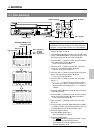
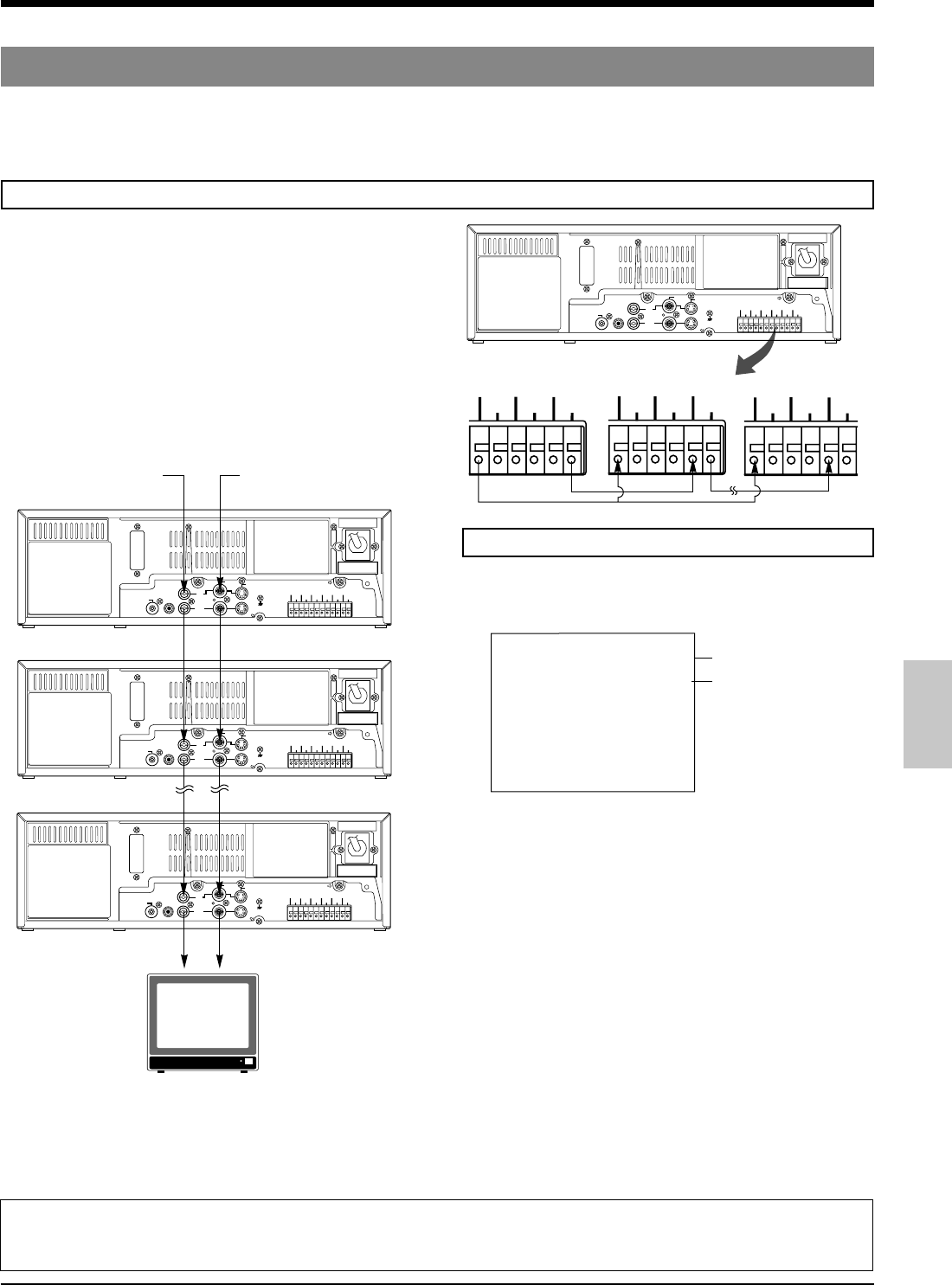
6-6 Series Recording
The series recording function facilitates recording over much longer periods using several connected AG-TL950P.
As soon as the tape ends in one VCR, the next VCR in the series starts recording. Using the counter end output function
enables smoother switchovers during series recording, mostly eliminating interruptions between tapes.
6 RECORDING
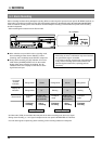
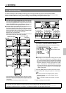
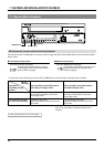
5 Connect the first VCR’s [SERIES REC OUT] terminal to the
second VCR’s [SERIES REC IN] terminal. Connect the
second VCR’s [SERIES REC OUT] terminal to the third
VCR’s [SERIES REC IN] terminal. Repeat for all connected
VCRs. Connect the VCR’s [COM] terminals as well.
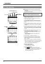
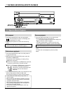
5 Connect a video camera and/or other source equipment to the
first VCR’s video and audio input connectors.
Connect the first VCR’s video and audio output connectors to
the second VCR’s video and audio input connectors. Connect
the second VCR’s video and audio output connectors to the
third VCR’s video and audio input connectors.
Repeat for all connected VCRs.
Connect the last VCR’s video and audio output connectors to
the monitor’s video and audio input connectors.
Connections
Video input signal
First VCR
Second VCR
Last VCR
Video output
Rear panel
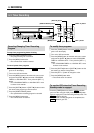
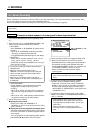
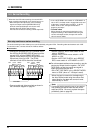
5 Normally the next VCR starts recording when the tape
ends. If the menu switch counter end output function is
on, a series recording signal is output when the selected
tape reel counter value is passed, and the next VCR starts
recording. Select the counter end value from “500”,
“1000” ... “9500” with the <CNT TAPE END> menu switch.
• The tape reel counter value from the beginning of the
tape to the end is about 5800 on a T-120 cassette tape.
(Reter to page 55.)
2 Press the [MENU] button to restore the normal screen.
3 Load cassettes with safety tab in place in all connected
VCRs.
5 To use the counter end output function, set the
counter to the tape reel counter display with the
[DISPLAY] button.
When a cassette is loaded, the counter is reset to
“0000”.
4 Start recording on the first VCR.
Audio input signal
Audio output
Monitor TV
AC~IN
RS-232C
CAM SW
OUT
ALARM
IN
COM
COM
ALARM
REC OUT
ALARM
RESET
TAPE
END OUT
WARNING
OUT
CLOCK
RESET IN
SERIES
RESET IN
SERIES
RESET OUT
CLOCK
RESET OUT
COM
WARNING
OUT
CLOCK
RESET IN
SERIES
REC IN
SERIES
REC OUT
CLOCK
RESET OUT
COM
WARNING
OUT
CLOCK
RESET IN
SERIES
REC IN
SERI
E
REC
O
CLOCK
RESET OUT
COM
WARNING
OUT
CLOCK
RESET IN
SERIES
REC IN
SERIES
REC OUT
CLOCK
RESET OUT
SPARE
MIC
IN
OUT
AUDIO
VIDEO
S-VIDEO
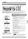
Operation
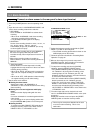
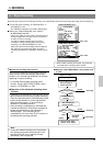
1 To activate series recording, set the <SRI/EXT REC>
menu switch in <SRI/EXT MODE> to “SERIES”.
(This setting should be done for all connected VCRs.)
Notes:
• If a cassette has not been loaded in any VCR in the series, series recording will stop when that VCR is reached.
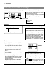
• If VCRs are connected in series as shown above, the second and subsequent VCRs will record the previous VCR’s on-screen
information in addition to their own. To avoid this, use a distributor to distribute only video signals to each VCR.
• During recording, the input video signals can be checked on a monitor.
• When the second and subsequent VCRs are turned on, input
audio can be checked on the monitor in the 2H/6H/L12H/L18H/
L24H modes.
During timelapse recording, audio cannot be checked.
Set to “SERIES”.
Set the counter value.