


-5-
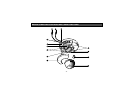
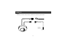
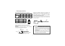
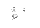
q DC Power Input Connector
This connector is for connecting the 12V DC power
supply cable.
w Video Output Connector
This connector is for connecting with the VIDEO IN
connector of the monitor.
e Cable Exit
Pass the cables through this concave when
installing on the ceiling/wall.
r Camera Mounting Screw Holes
Mount the camera by fixing with screws through
these holes.
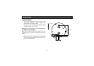
t Lens
Rotate this lens to adjust the focus.
y Rubber Cap (standard accessory)
Attach this cap on the camera mounting screw
hole.
u Dome Cover
This protects the camera head.
i Panel Cover
Open this cover when installing the camera or con-
necting the cables.
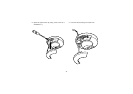
o Camera Head
This adjusts the tilting angle of the camera.
!0 Lens Holder
These holders bring the picture in an upright posi-
tion on the monitor screen.
!1 Panning Table
This adjusts the panning angle of the camera.
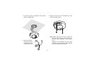
!2 Cable Hole
Pass the cables through this hole when installing
on the ceiling/wall.
!3 Panel Cover Detaching Slit
Insert a tool, such as a screwdriver (−), into this slit
to open the panel cover.
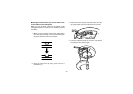
Cautions:
• Connect to 12 V DC (10.5 V-16 V) class 2
power supply only. Make sure to connect the
grounding lead to the GND terminal when
the power is supplied from a 12 V DC power
source.
• To prevent fire or electric shock hazard, use
a UL listed wire VW-1, style 1007 cable for
the Input Terminal.