


Precautions for installation
Panasonic assumes no responsibility for injuries or
property damage resulting from failures arising out
of improper installation or operation inconsistent
with this documentation.
Power supply
This product has no power switch. Use a power supply
device equipped with the ON-OFF switch for servicing.
When the power cable of the product is connected to the
power supply device, the power will be supplied to the
product. When the product is supplied, the product will
perform panning, tilting, zooming and focusing.
Before cleaning the product, make sure that the power
cable is not connected to the main power supply.
Installation area for this product
Select an appropriate place for the installation area (such
as a strong wall or ceiling) in your particular environment.
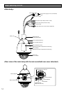
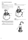
Mounting method for this product
• This product is designed to be usedas a pendant
mount camera. If the product is mounted on a desk-
top or at a slant, it may not work correctly or its life-
time may be shorten.
• Mounttheproducthorizontallysothatthedomesec-
tion faces downward.
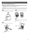
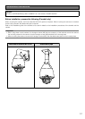
Ceiling pendant type mount bracket/Wall mount
bracket
• When pendant-mounting on a ceiling on a bracket
that is locally procured, use the attachment pipe.
• When installing on a wall, use Wall Mount Bracket
WV-Q122 (option). When this product and camera
mount bracket are mounted on a ceiling or a wall, use
the screws described in the following table. The
screws that secure the product are not supplied.
Prepare them according to the material and strength
of the area where the product is to be installed.
<Installing conditions>
Camera
Weight
Approx. 4.6 kg {10.15 lbs}
Appropriate mount bracket
Model No. WV-Q122 (E model only)
Weight
Approx. 2 kg {4.42 lbs}
Mount type On wall
Part to be mounted on a ceiling/wall
Recommended screw M8
Number of screw 4
Pull-out capacity of a
single screw
823 N {84 lbf}
• Ensurethatthemountingsurface,anchorandscrews
are sufficiently strong.
• Do notmount the producton a plasterboard or a
wooden section because they are too weak. If the
product is unavoidably mounted on such a section,
the section shall be sufficiently reinforced.
Do not place this product in the following places:
• Locationswhereachemicalagentisusedsuchasa
swimming pool
• Locations subject to humidity, dust, steam and oil
smoke
• Locationswherearadiation,anX-ray,astrongradio
wave or a strong magnetic field is generated
• Locationswherecorrosivegasisproduced,locations
where it may be damaged by briny air such as sea-
shores
• Locations where the temperature is not within the
specified range (☞ page 36).
• Locations subject to vibrations (This product is not
designed for on-vehicle use.)
• Locations subject to condensation as the result of
severe changes in temperature (In case of installing
the product in such locations, the dome cover may
become foggy or condensation may be caused on
the cover.)
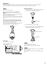
Screw tightening
• The screws and bolts must be tightened with an
appropriate tightening torque according to the materi-
al and strength of the installation area.
• Donotuseanimpactdriver.Useofanimpactdriver
may damage the screws or cause tightening exces-
sively.
• Whenascrewistightened,makethescrewataright
angle to the surface. After tightening the screws or
bolts, perform visual check to ensure tightening is
enough and there is no backlash.
Remove the cover film from the dome section of the
dome cover after the installation is complete.
Be sure to remove this product if it is not in use.
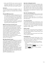
When noise disturbance may happen
Conduct the power distribution work to keep a distance of
1 m {3.28 feet} or more from the 120 V (for U.S. and
Canada) or 220 V - 240 V (for Europe and other countries)
power line. Or conduct the electric conduit work sepa-
rately.
12