


Configuration Options
4-19
9783-A2-GB20-00
July 2000
Configuring Circuit and DLCI Records
Circuit and DLCI records can be created and modified, and PVCs created based
on existing DLCIs, using the Network Circuit Records screen and the Data Ports
DLCI Records screen:
Main Menu
→
Configuration
→
Network
→
Circuit Records
Main Menu
→
Configuration
→
Data Port
→
DLCI Records
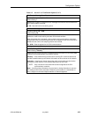
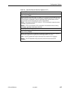
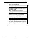
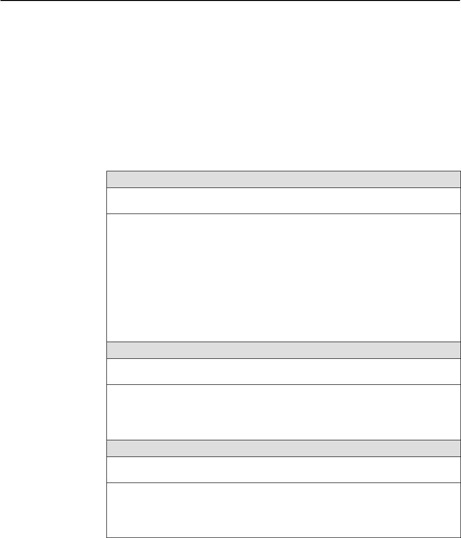
Table 4-9. DLCI Record Options (1 of 3)
DLCI Number
Possible Settings: 16 – 1007
Default Setting: Initially blank; no default.
Specifies the number for the DLCI in the DLCI record. The parameter determines which
DLCI record is used for transferring data on a particular frame relay interface. DLCI
numbers range from 0 to 1023. However, the numbers 0 to15 and 1008 to 1023 are
reserved. Entry of an invalid number results in the error message Value Out of
Range (16 – 1007). If the DLCI number is part of a connection, this field is read-only.
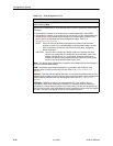
NOTES: – If a DLCI number is not entered, the DLCI record is not created.
– The DLCI number entered must be unique for the interface.
– Changing settings for this configuration option causes the FrameSaver
unit to abort any active frame relay tests.
16 – 1007 – Specifies the DLCI number (inclusive).
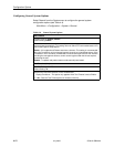
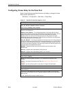
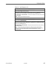
VPI,VCI Number (VPI)
Possible Settings: 0 – 15
Default Setting: Initially blank; no default.
Specifies the VPI. Entry of an invalid number results in the error message Value Out
of Range (0 – 15). The VPI/VCI must be unique on the ATM link.
Display Conditions
– This option does not appear for the user data port.
0 – 15 – Specifies the VPI.
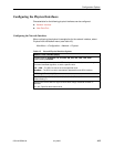
VPI,VCI Number (VCI)
Possible Settings: 32 – 255
Default Setting: Initially blank; no default.
Specifies the VCI. Entry of an invalid number results in the error message Value Out
of Range (32 – 255). The VPI/VCI must be unique on the ATM link.
Display Conditions
– This option does not appear for the user data port.
32 – 255 – Specifies the VCI.