


Model 3088 Quick Start Guide
5
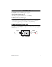
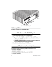
Connect the serial cable to the RocketLink-G serial port as follows:
1.
Attach the male connector of the serial cable to the female serial connector on the RocketLink-G.
2.
Attach the other end of the cable to the serial connector on the local serial NTU.
Note
The V.35 interface is wired as a DCE. To connect the V.35 interface to third-party equipment wired as a
DCE, you must use a tail-circuit cable. You can purchase a tail-circuit cable from a datacom-supply ven-
dor. A tail-circuit cable will cross-over the necessary V.35 signals so that the two DCE interfaces
can communicate.
Note
You can connect the V.35 interface to an M/34 connector using Patton’s Model 2-34F25M
interface adapter.
Note
The X.21 interface is wired as a DCE. If you need to change the orientation ti DTE, refer to section “
Con-
necting the Model 3088/D (X.21) Serial Interface”
in the
Model 3088 Series Getting Started Guide,
The X.21 interface requires a cable with a male DB-15 connector.
Note
You can configure the T1/E1 interface to either recover the network clock from the T1/E1 line or supply
the network clock for the T1/E1 line.
5.0 Additional information
For detailed information about installing, configuring, operating, and troubleshooting, refer to the
Model 3088
Series Getting Started Guide
on the enclosed Patton CD-ROM or at
www.patton.com/manuals
.
A.0 Compliance Information
A.1 Compliance
EMC:
•
FCC Part 15, Class A
•
EN55022, Class A
•
EN55024
•
GOST-R
Safety:
•
UL 60950-1/CSA C22.2 N0. 60950-1
•
IEC/EN60950-1
•
AS/NZS 60950-1
•
GOST-R
PSTN Regulatory:
•
FCC Part 68
•
CS03