


C1963M (8/04) 9
CONNECTIONS
POWER
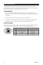
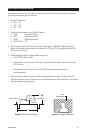
To connect to the power supply:
1. Strip at least .50 inch (13 mm) from the power cord to expose the wires.
2. Insert the three wires into the holes in the terminal strip until they snap into place.
3. Confirm that the cord is connected to terminal securely by lightly tugging on the cord.
If you are wiring more than one camera to the same transformer, connect one side of the trans-
former to the same terminal on all cameras, and connect the other side of the transformer to the
remaining terminal on all cameras. Failure to connect all of the cameras the same way will cause
the cameras to be out of phase with each other and may produce a vertical roll when switching
between cameras.
VIDEO
Connect a video cable to the SIGNAL OUT connector (BNC) on the rear of the camera. Refer to
Table A for the type of video coaxial cable to use.
Table A. Video Coaxial Cable Requirements
Cable Type* Maximum Distance
RG59/U 750 ft (229 m)
RG6/U 1,000 ft (305 m)
RG11/U 1,500 ft (457 m)
*Minimum cable requirements:
75 ohms
All-copper center conductor
All-copper braided shield with 95% braid coverage