


6 Pelco Manual C1496M-A (2/02)
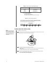
Total vA 20 18 16 14 12 10
10 vA 283 ft 451 ft 716 ft 1142 ft 1811 ft 2880 ft
(86) (137) (218) (348) (551) (877)
Table B. 24 VAC Wiring Distances
The following are the recommended maximum distances for 24 VAC
with a 10-percent voltage drop. (Ten percent is generally the maximum
allowable voltage drop for AC-powered devices.)
Wire Gauge
Table A. Video Coaxial Cable Requirements
Cable Type* Maximum Distance
RG59/U 750 ft (229 m)
RG6/U 1,000 ft (305 m)
RG11/U 1,500 ft (457 m)
* Minimum cable requirements:
75 ohms impedance
All-copper center conductor
All-copper braided shield with 95% braid coverage
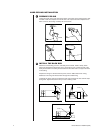
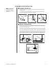
CAMERA AND LENS INSTALLATION
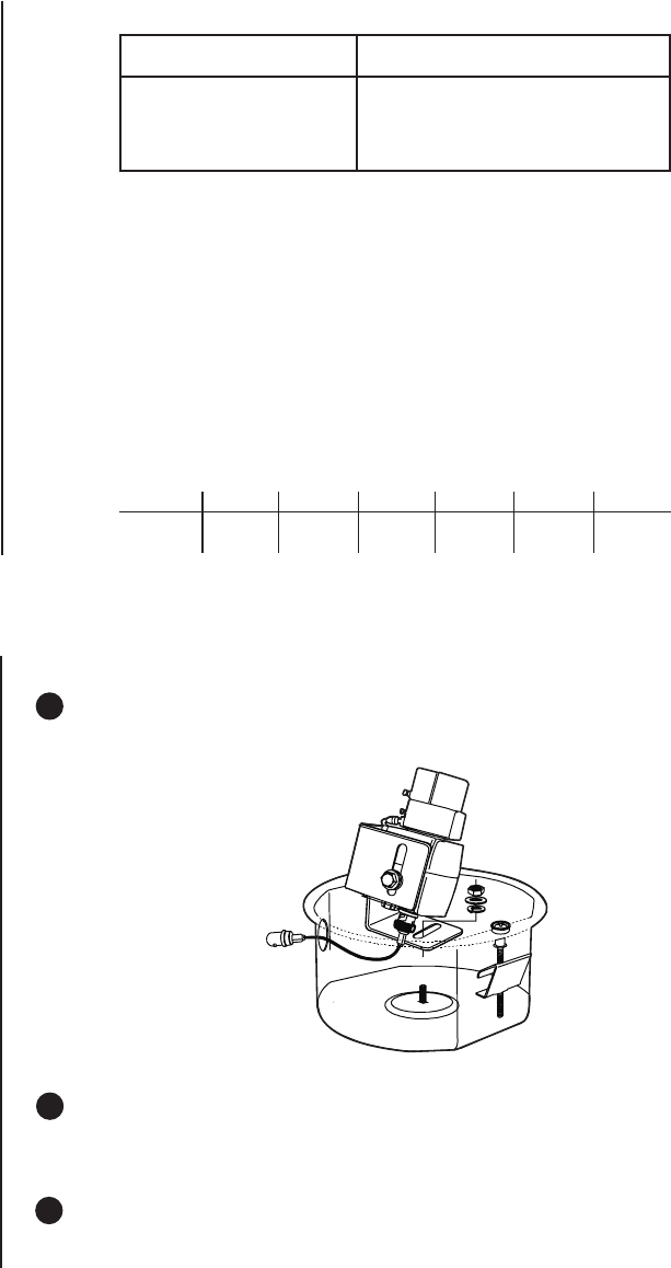
To install the camera and lens:
1 Install the miniature coaxial cable on the camera. Attach the camera and lens to the tilt
table with the 1/4-20 screw and washers (supplied).
2 To ensure that the lens will not hit the lower dome:
• Place the lower dome over the back box with the camera and lens installed (do not
attach dome).
• If the lens touches the lower dome, adjust the tilt table assembly.
3 Refer to the manual supplied with the camera and lens for the following information:
• How to connect power and video wiring
• How to make camera and lens adjustments
20130
NOTE:
If the camera and
lens are already installed,
refer to the camera and lens
manuals for information on
wiring and operating your
equipment.