14 Pelco Manual C342M-PSA (11/98)
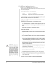
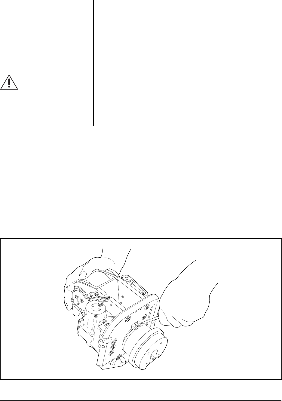
3. Adjust the pan limit stops.
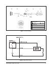
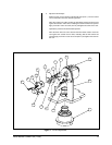
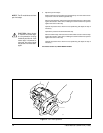
Refer to Figure 8 for the location of the pan limit stops. Turn the control unit on
and pan the unit to the desired right limit stop.
Move the right limit stop until it touches the limit switch actuator. Push the stop
against the actuator until it clicks, indicating that the limit switch has opened.
Tighten the screw on the stop.
Operate the pan/tilt unit to check for exact positioning and adjust the stop if
necessary.
Operate the pan/tilt to the desired left limit stop.
Move the left limit stop until it touches the limit switch actuator. Push the stop
against the actuator until it clicks, indicating that the limit switch has opened.
Tighten the screw on the stop.
Operate the pan/tilt unit to check for exact positioning and adjust the stop if
necessary.
Proceed to Section 3.5, FINAL INSTALLATION.
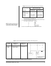
NOTE:
The SL model does not have
pan limit stops.
CAUTION:
Never loosen
or remove the center stop.
It is for protection of wiring
inside the pan/tilt unit. If the
center stop is loosened or
removed, the wiring inside
the pan/tilt unit will be dam-
aged.
Figure 8. Pan Limit Adjustment
00084


