Pelco Manual C534M (2/98) 5
2.2 CIRCUIT DESCRIPTION
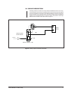
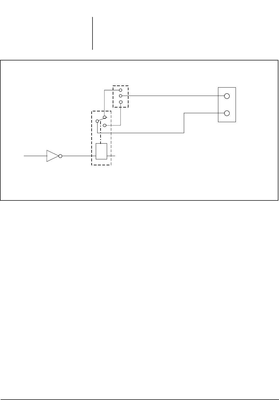
The Relay Interface consists of two relay cards (with additional room for two more),
one motherboard, and one power supply board. The unit receives TTL level signals
from the GPI SPINC card (located in the CM9750/CM9760 Controller) through the
50-pin connector on the rear panel of the unit. This TTL signal is then inverted and
applied to the corresponding relay to close the contact. The position of the strap
determines the condition of the output. Refer to Figure 2.
Figure 2. Relay Output Functional Schematic
3
2
1
JUMPER
RELAY
+12 VDC
TTL IN
RELAY
OUTPUT
TYPICAL FOR ALL
RELAY CIRCUITS
NO
NC
COM
MAX DC CURRENT 1 AMP


