Pelco Manual C534M (2/98) 7
3.4 WIRING THE RELAY OUTPUTS
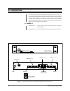
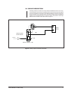
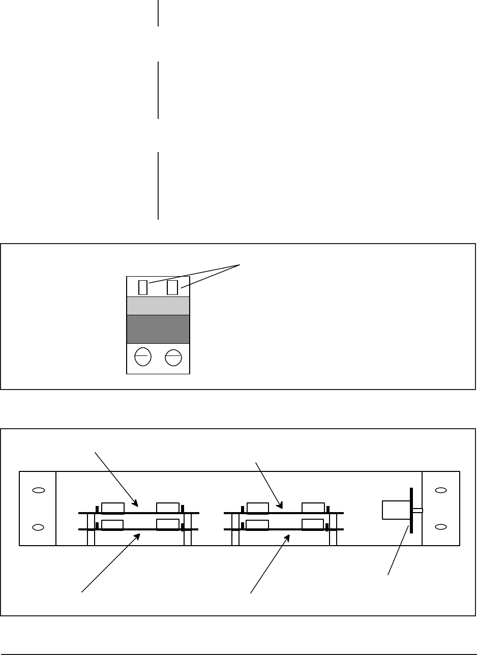
Refer to Figure 3. Select the desired relay output and insert the wires to be used
into the square holes in the terminal. Tighten the screws until the wires are properly
secured.
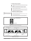
3.5 INSTALLING AND REMOVING THE RELAY CARDS
To install or remove any of the relay cards, remove the top cover to the unit. Refer to
Figure 4 for the identification of each board.
To remove a specific board, remove the mounting hardware (four Phillips screws)
and disconnect the two ribbon cables connecting the relay card to the mother board.
The card can now be removed from the unit.
3.6 CHANGING THE JUMPER LOCATIONS
Remove the desired board(s) as described Section 3.5.
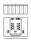
Next, determine which output you wish to change. Once decided, refer to Table B
for the corresponding board and jumper.
Once the proper board has been determined, gain access to the desired jumper and
place in the desired setting. Refer to Figure 5 for the jumper pin assignments.
NOTE:
Each board is the same and
therefore has the same silkscreen
identification for the relays and jump-
ers.
BOARD A (OUTPUTS 1-8)
BOARD C (OUTPUTS 17-24)
BOARD B (OUTPUTS 9-16) BOARD D (OUTPUTS 25-32)
POWER SUPPLY
BOARD
Figure 3. Wiring External Equipment to the Relay Outputs
Figure 4. Relay Card Location
RELAY 32
TYPICAL FOR ALL
RELAY OUTPUTS
INSERT CONNECTIONS
FROM EXTERNAL EQUIPMENT


